3 minute read
DIAGNOSTIC TOOLS & PROCEDURES


Troubleshooting Procedures
Determining That a Fault Exists
Before beginning any troubleshooting procedure, be certain that a problem actually exists. If possible, talk to the driver or the person who noticed the problem, and try to obtain as much information as possible. In some cases, the only evidence of a fault is a verbal complaint.
After determining that an active fault does exist, follow the troubleshooting sequence listed in this manual. The procedures are organized according to the diagnostic code.
Locating Diagnostic Blink Code Information
Once the diagnostic code has been displayed, there are several places to find information explaining what the diagnostic code actually means.
r Table of Contents (front of the book) r Index (back of the book)
These sources list the pages that contain information on a particular diagnostic code.
Performing Diagnostic Tests
Once a fault has been logged, whether active or inactive, the tests for that particular fault must be completed, step by step, in the order in which they are listed. This allows you to logically move toward a solution to the problem.
r Follow the tests exactly as they are outlined.
r Start at the beginning of each sequence, and perform each test in the order in which it is outlined.
r Do not skip steps or attempt to shortcut the test procedure.
r The results of each test will identify possible causes of the problem, or will determine which test to perform next.
Not all tests are performed in sequence. For example, the results of a particular test may specify performing Test 9 after Test 4, skipping Tests 5–8.
Page 25
DIAGNOSTIC TOOLS & PROCEDURES
Service Hints
Following the recommendations discussed in this section may save considerable time and effort when performing diagnostic procedures.
Test Procedures
When instructed in a test procedure to check continuity or voltage from one pin to each of the others, this means one at a time, not all at the same time.
If instructed to disconnect the harness connector from the V-MAC II module during any of the test procedures, the ignition key must be in the OFF position, and the accessory relay must be OFF (make sure the serial link jumper is not installed). Failure to observe this caution can cause internal electrical damage to the module.
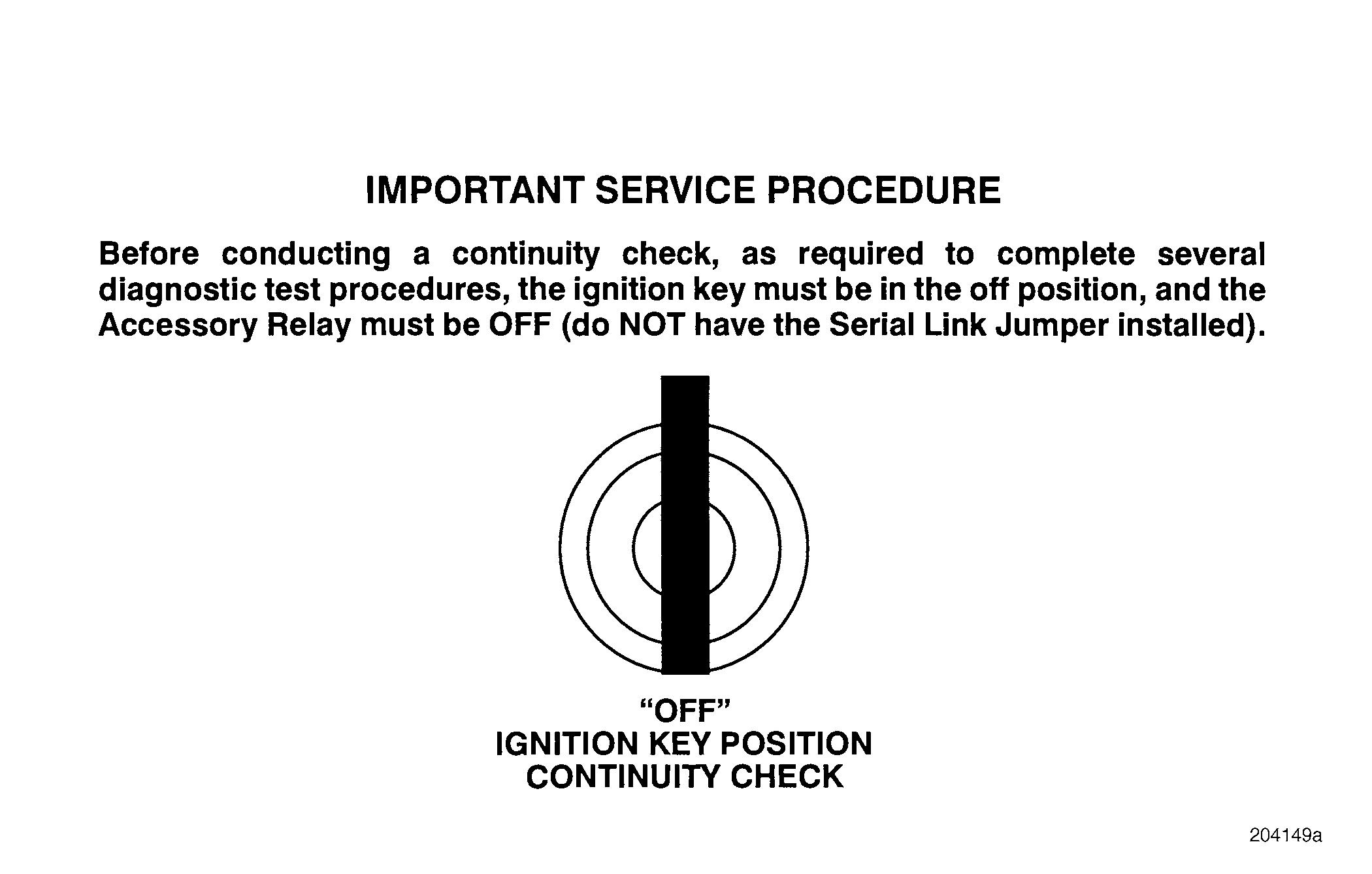
Before conducting a continuity check, as required in several test procedures, the ignition key must be in the OFF position.
When inserting a test probe into a connector, do not force the probe into the connector. Doing so can damage to the connector.
DIAGNOSTIC TOOLS & PROCEDURES
Wire and Connectors
When performing electrical diagnostic tests, it is always a good practice to move (wiggle) the electrical wires and connectors. This will help identify the instances where wires are making poor or intermittent contact. When working with the V-MAC II system, this may cause a fault to be logged, which will help to identify the problem.
In any test procedure that requires disconnecting a connector, visually inspect both sides of the connector for debris, broken, bent or missing pins, or broken connector housings.
Many electrical problems are caused by dirty, loose or disconnected connectors. Intermittent problems usually indicate a loose or poor connection, or marginal adjustment on a component. Before beginning any test sequence: r Check the condition of the wires and connectors. r Check the batteries for correct voltage. r Examine each harness for places where sharp metal edges may have cut through. r Check for damaged connectors or wires which may have pulled out of connector terminals. r Inspect seals on the connectors for looseness, cracks, missing parts, etc. r Make sure there is no grease on the connectors. If any grease is found, it should be cleaned off, as improper sealing can cause failures.
The design of MACK wiring harnesses allows individual wire repair or replacement. Replacement of a wiring harness should only be necessary when major damage has occurred to the harness.
System Components
Before replacing components, retest the circuit to confirm that an active fault still exists. Unless otherwise specified, “replace” means to install a new component.
V-MAC II Module
The least likely component to fail is the V-MAC II module.
In any diagnostic test procedure where the instructions call for replacing the V-MAC II module, do not reprogram the replacement module until you are certain that the problem has been solved. If replacing the module does solve the problem, it is essential that the module is programmed with the vehicle operating parameters. Failure to program the replacement module will result in reduced system performance. To program the module with vehicle and customer data, follow the instructions which are supplied with the Pro-Link 9000 or the PC diagnostic software package. It is essential that the module be reprogrammed with the MACK DATA PROGRAMMING software (see your MACK distributor). Do not program a replacement V-MAC II module with MACK DATA PROGRAMMING until it is confirmed that the new V-MAC II module has corrected the problem. Reprogramming with MACK DATA PROGRAMMING executes the password protection function which assigns a new password to the vehicle. This process is irreversible. If the old module is not the problem and it is reinstalled on the vehicle, it cannot be reprogrammed because the password will no longer match
Page 27


