
6 minute read
DIAGNOSTIC CODE 3-2


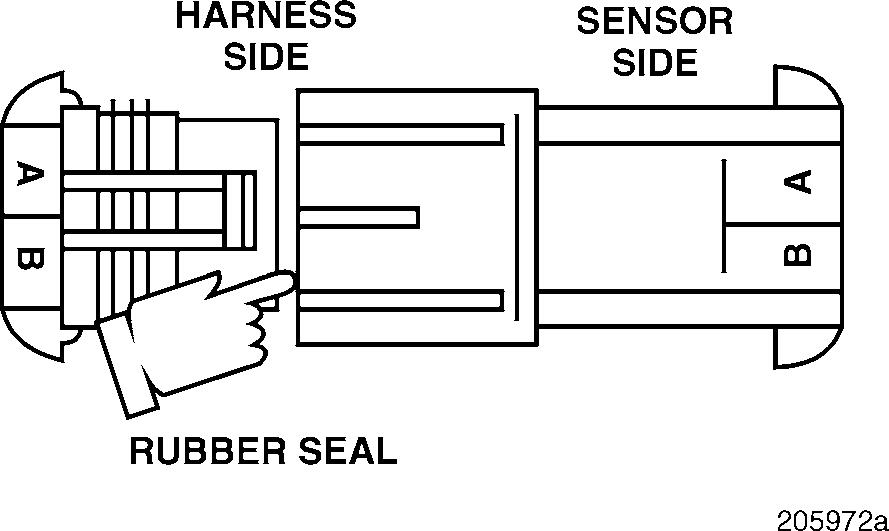
Checking for a short to ground in the sensor
Test 4
Checking for proper RPM sensor adjustment
1.Check that the sensor is properly adjusted in the flywheel housing. For proper adjustment, turn the sensor in by hand until it bottoms. Then back it out exactly 1 turn. Torque the jam nut to 15 lb-ft (20 N•m).
If the sensor is adjusted properly, proceed to Test 8.
If the sensor is not adjusted properly, readjust the sensor. Retest to be sure the problem has been corrected.
Test
8
Checking for a short to voltage on the RPM PLUS line
1.Check for
2.Check for continuity
If there is continuity, replace the sensor. Retest to be sure the problem has been corrected.
If there is no continuity, proceed to Test 4.
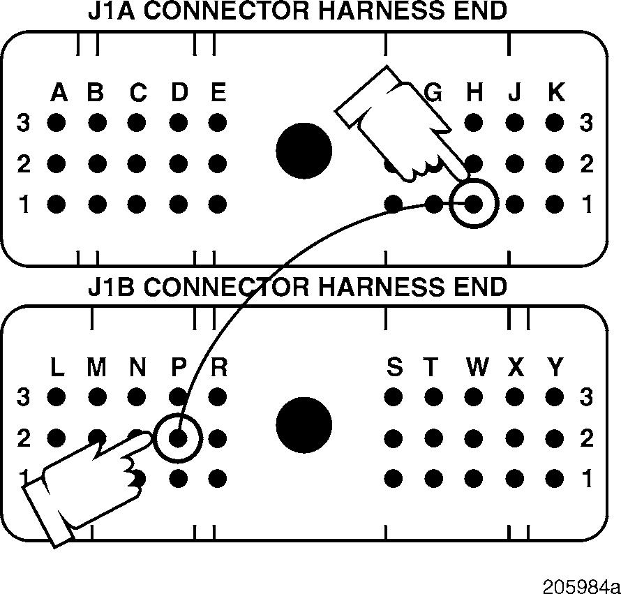
1.Disconnect the and J1B connectors from the V-MAC II module.

2.Connect the serial link jumper into the serial communication port.
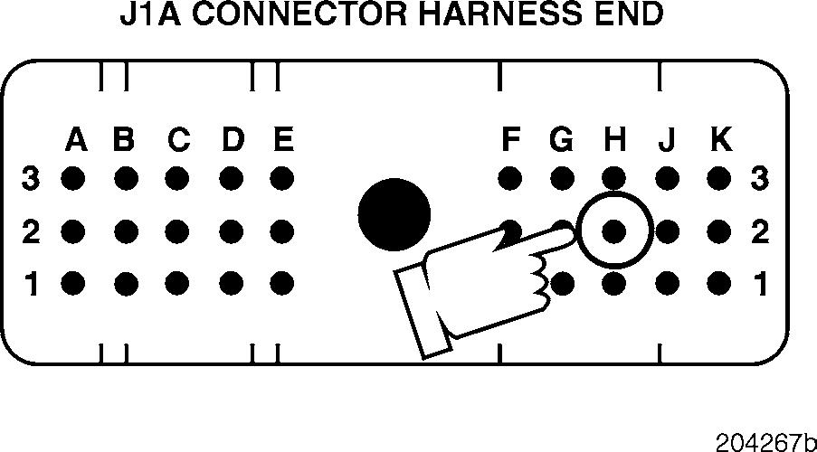
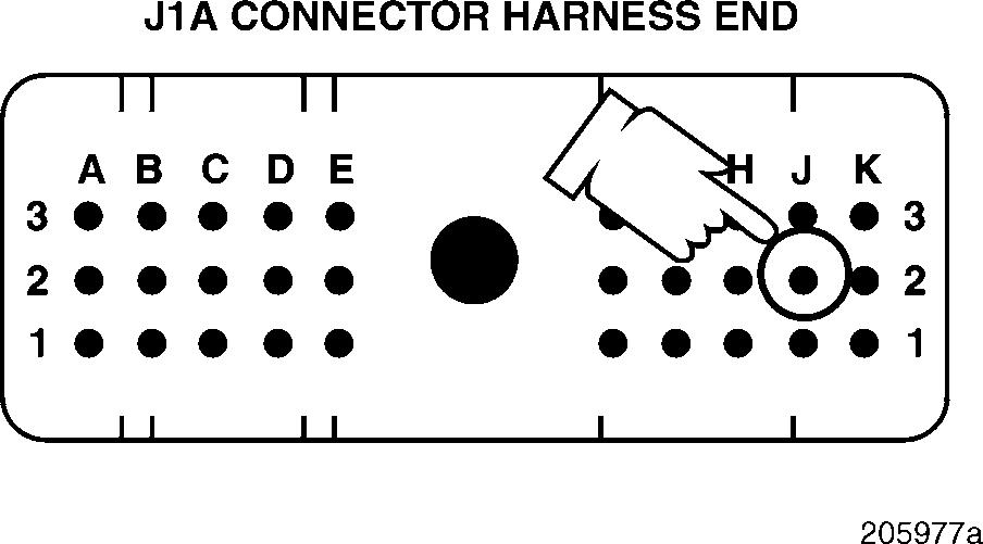
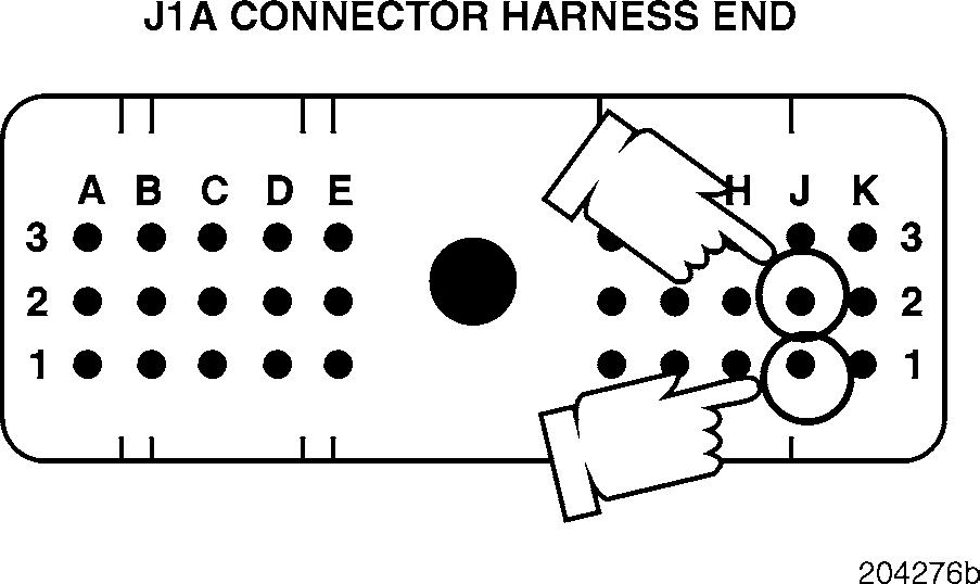
3.Measure the voltage from J1A connector pin H1 (the RPM/TDC PLUS [+] line) to a good ground.
If the voltage is greater than 0.5 volts, the line is shorted to another line in the harness. Locate and repair the short. Retest to be sure the problem has been corrected.
If the voltage is less than 0.5 volts, proceed to Test 16.
Test 16
DIAGNOSTIC CODE 3-2
Checking for a short to voltage on the RPM MINUS line
1.Measure the voltage from J1A connector pin H2 (the RPM/TDC MINUS [ ] line) to a good ground.
If the voltage is greater than 0.5 volts, the line is shorted to another line in the harness. Locate and repair the short and replace the V-MAC II module. Retest to be sure the problem has been corrected.
If the voltage is less than 0.5 volts, proceed to Test 32.
Test 32
Checking for a pin-to-pin short in the harness
1.Disconnect the serial link jumper.
2.Disconnect the J2 connector from the V-MAC II module.
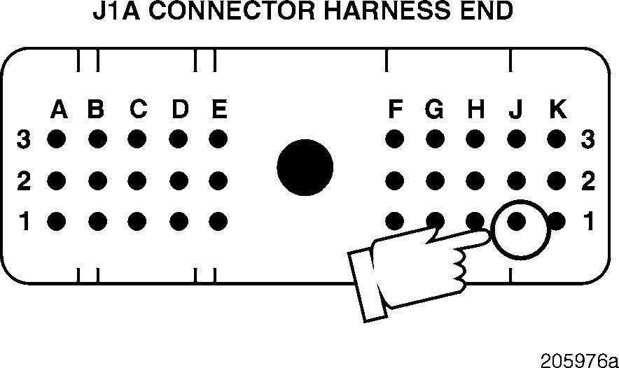
3.Check for continuity between J1A connector pin H1 (the RPM/TDC PLUS [+] line) and each of the other pins (one at a time) on the J1A, J1B and J2 connectors.
4.Check for continuity between J1A connector pin H2 (the RPM/TDC MINUS [ ] line) and each of the other pins (one at a time) on the J1A, J1B and J2 connectors.
If there is continuity with another pin, repair the short in the harness between the pins which showed continuity. Retest to be sure the problem has been corrected.
If there is no continuity, proceed to Test 64.
If there is continuity with J1B connector pins P1 and P2 (ground pins), there may also be continuity with other pins. Repair the short to pins P1 and P2 first. Then retest to be sure the problem has been corrected.
Test 64
DIAGNOSTIC CODE 3-2
Checking for an open in the harness
Test 128
Checking for an open on the sensor side of the connector
1.Connect
2.Check for
If there is continuity, proceed to Test 128.
If there is no continuity, proceed to Test 129.
1.Remove
2.Reconnect the RPM sensor.
3.Measure the resistance between pins J1A connector pins H1 (the RPM/TDC PLUS [+] line) and H2 (the RPM/TDC MINUS [ ] line).

If the resistance is between 100 and 500 ohms, proceed to Test 256.
If the resistance is not between 100 and 500 ohms, the RPM PLUS [+] or MINUS [ ] lines are open or faulty at the connector. Repair the connector if possible, otherwise, replace the sensor Retest to be sure the problem has been corrected.
Test 129
DIAGNOSTIC CODE 3-2
Checking for an open in the RPM line on the module end of the harness
Test 256
Checking for a defective module or loose connector
1.With the ignition key in the OFF position, reconnect the V-MAC II connectors.
2.Start the engine.
If blink code 3-2 is still active, check the V-MAC II module and connector for dirt, loose or broken pins, or repairable damage. If no repairable conditions are evident, replace the V-MAC II module. Retest to be sure the problem has been corrected.
If blink code 3-2 is not active, the procedures have corrected the problem. Check all connectors to ensure proper connections.
If there is continuity, repair the open in the RPM line (pin H2).
If there is no continuity, select another chassis ground. If there is still no continuity, repair the RPM line (pin H1). Retest to be sure the problem has been corrected.
DIAGNOSTIC CODE 3-4
DIAGNOSTIC BLINK CODE 3-4
TIMING EVENT MARKER (TEM) TESTS
When performing electrical tests, it is important to wiggle wires and connectors to identify intermittent connection problems.
Blink Code 3-4
PID
SID 1 FMI 2
MID 142
Name Timing (TEM) Sensor
Failure Data erratic, intermittent or incorrect
The engine must be running to see an active fault on the TEM circuit.
Test 1
Checking for an open or short in the sensor
1.Turn
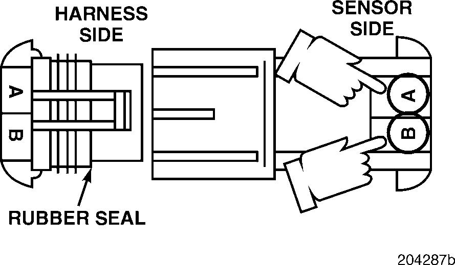
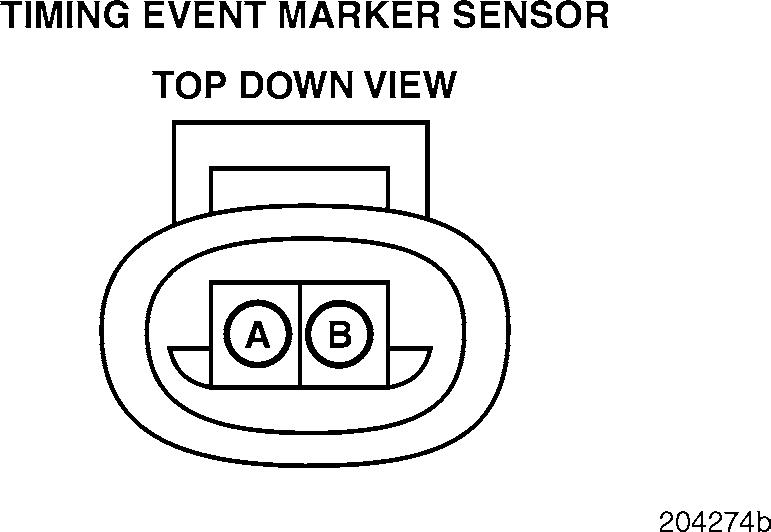
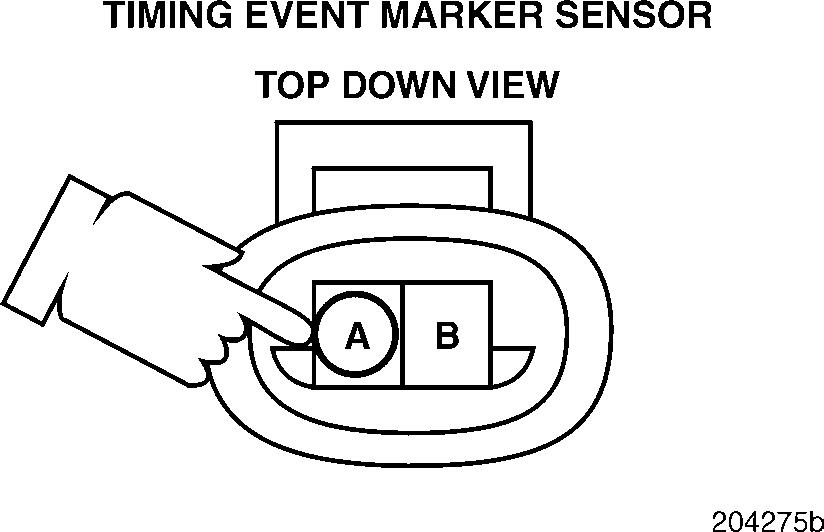
2.Measure the resistance between pins A and B on the sensor.
If the resistance is between 100 and 500 ohms, proceed to Test 2.
If the resistance is not between 100 and 500 ohms, repair the connector or replace the sensor. Retest to be sure the problem has been corrected.
Test 2
DIAGNOSTIC CODE 3-4
Checking for a short to ground in the sensor
1.Disconnect the J1A and J1B connectors from the V-MAC II module.
2.Connect the serial link jumper into the serial communication port.
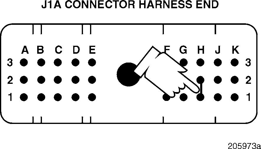
3.Measure the voltage from J1A connector pin J1 (the TEM PLUS [+] line) to a good ground.
4.Measure the voltage from J1A connector pin J2 (the TEM MINUS [ ] line) to a good ground.
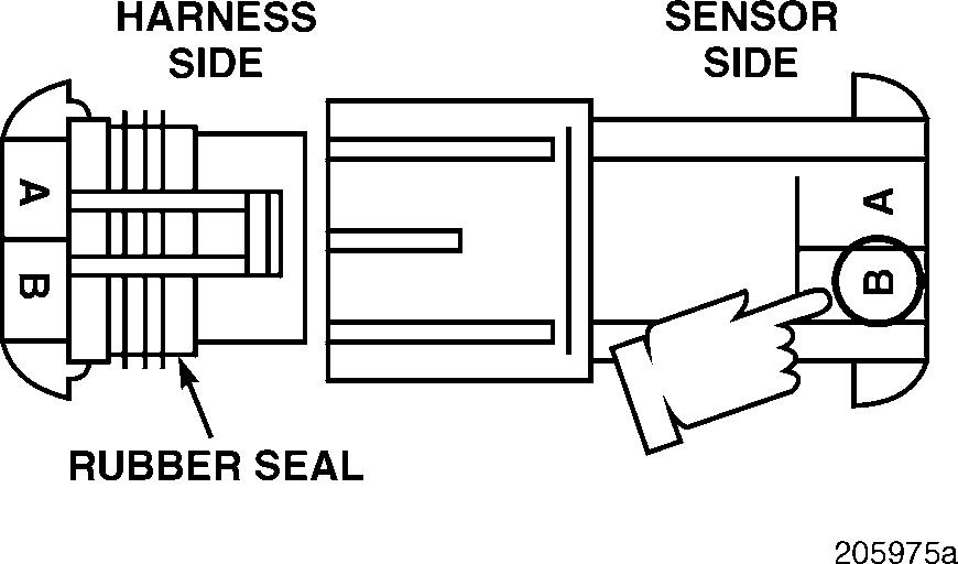
1.Check for continuity from harness connector pin A (the signal [+] line) to a good ground.
If there is continuity, replace the sensor. Retest to be sure the problem has been corrected. If there is no continuity, proceed to Test 4.
Test 4
Checking for a short to voltage in the harness
If the voltage on either line is greater than 0.5 volts, the line is shorted to another line in the harness. Locate and repair the short. Retest to be sure the problem has been corrected.
If the voltage on both lines is less than 0.5 volts, proceed to Test 8.
To install the TEM sensor, coat the sensor threads with Silastic. Then turn the sensor body into the pump until it bottoms out. Tighten the jam nut to 22.5 lb-ft (30.5 N•m) of torque.
Test 8
Checking for proper TEM sensor adjustment
1.Check that the sensor is properly seated in the injection pump.
If it is properly seated, proceed to Test 16.
If it is not properly seated, follow the instructions in the above note. Then retest to be sure the problem has been corrected.
Test 16
Checking for a pin-to-pin short in the harness
If there is continuity with J1B connector pins P1 and P2 (ground pins), there may also be continuity with other pins. Repair the short to pins P1 and P2 first. Then retest to be sure the problem has been corrected.
Test 32
Checking for an open in the harness
1.Disconnect the serial link jumper.
2.Disconnect the J2 connector from the V-MAC II module.
3.Check for continuity between pin J1 (the TEM PLUS [+] line) and each of the other pins (one at a time) on the J1A, J1B and J2 connectors.
4.Check for continuity between pin J2 (the TEM MINUS [ ] line) and each of the other pins (one at a time) on the J1A, J1B and J2 connectors.
If there is continuity with another pin, repair the short in the harness between the pins which showed continuity. Retest to be sure the problem has been corrected.
If there is no continuity, proceed to Test 32.
1.Connect a jumper between J1A connector pins J2 and J1.
2.Check for continuity between harness connector pin A (the signal [+] line) and harness connector pin B (the ground [ ] line), on the sensor side of the connector. If there is continuity, proceed to Test 64. If there is no continuity, proceed to Test 65.

Test 64
DIAGNOSTIC CODE 3-4
Checking for an open on the sensor side of the connector
Test 65
Checking for an open in the TEM PLUS (+) line on the module end of the harness
1.Remove the jumper between J1A connector pins J2 and J1.
2.Reconnect the TEM sensor.
3.Measure the resistance between J1A connector pins J1 (the TEM PLUS [+] line) and J2 (the TEM MINUS [ ] line).
If the resistance is between 100 and 500 ohms, proceed to Test 128.
If the resistance is not between 100 and 500 ohms, the TEM PLUS [+] or MINUS [ ] lines are open or faulty at the connector. Repair the connector if possible. Otherwise, replace the sensor. Retest to be sure the problem has been corrected
1.Connect a jumper between J1A connector pin J1 and J1B connector pin P2.
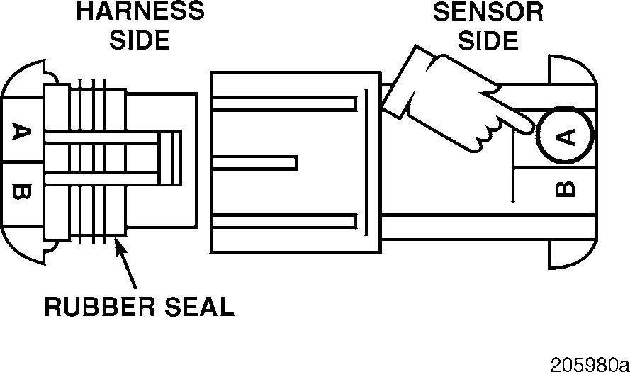
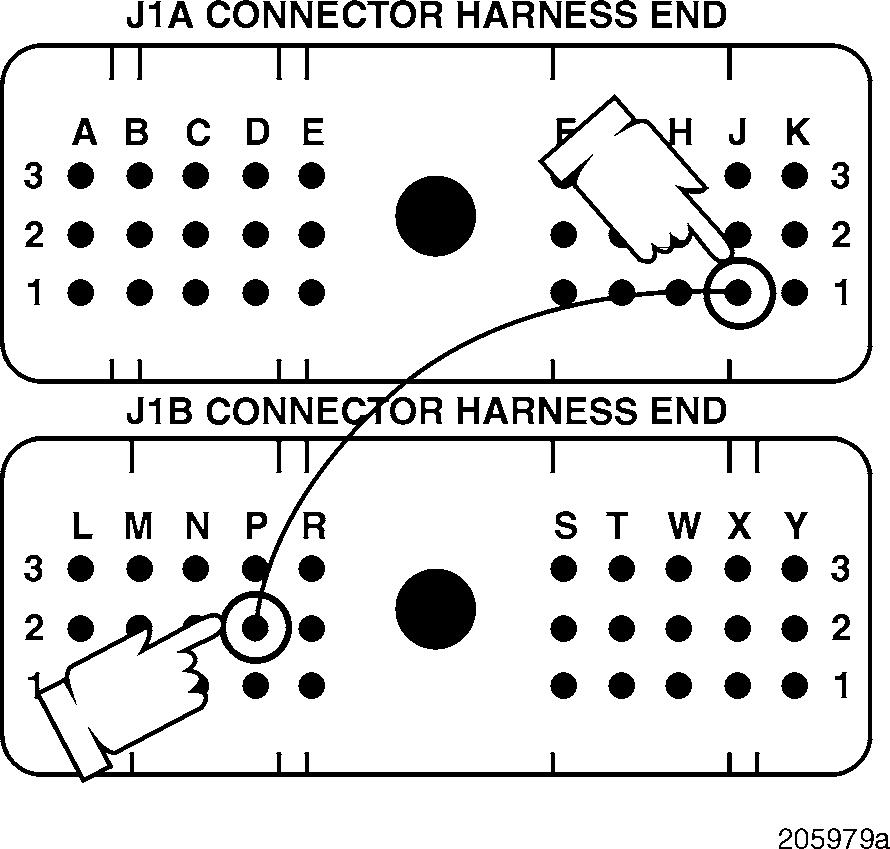
2.Check for continuity from harness connector pin A (the signal [+] line), on the sensor side of the connector, to a good ground.
If there is continuity, repair the open in the TEM MINUS [ ]line (pin J2)
If there is no continuity, select another chassis ground. If there is still no continuity, repair the TEM PLUS [+] line (pin J1). Retest to be sure the problem has been corrected.


