1 minute read
DIAGNOSTIC CODE 3-5 (ELECTRICAL)


Test 8
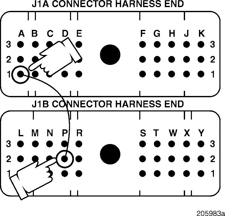
Checking for a pin-to-pin short in the harness
If there is continuity with J1B connector pins P1 and P2 (ground pins), there may also be continuity with other pins. Repair the short to pins P1 and P2 first. Then retest to be sure the problem has been corrected.
Test 16
Checking for an open in the harness
1.Disconnect the serial link jumper.
2.Disconnect the J2 connector from the V-MAC
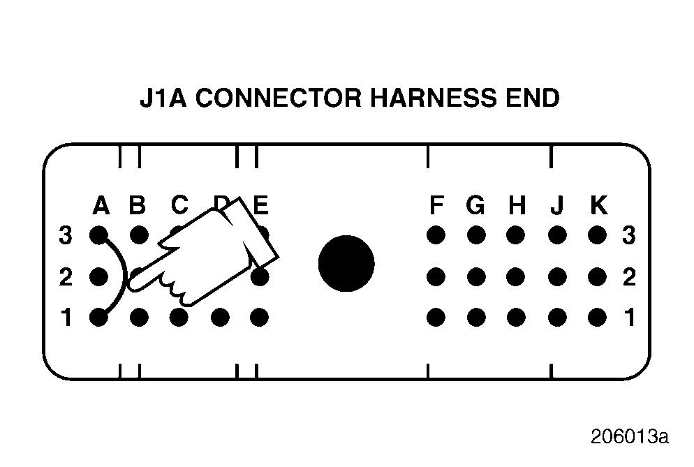
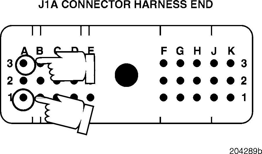
3.Check for continuity between J1A connector pin A1 (the timing solenoid PLUS [+] line) and each of the other pins (one at a time) on the J1A, J1B and J2 connectors.
4.Check for continuity between J1A connector pin A3 (the solenoid MINUS [ ] line) and each of the other pins (one at a time) on the J1A, J1B and J2 connectors.
If there is continuity with another pin, repair the short in the harness between the pins which showed continuity. Retest to be sure the problem has been corrected.
If there is no continuity, proceed to Test 16.
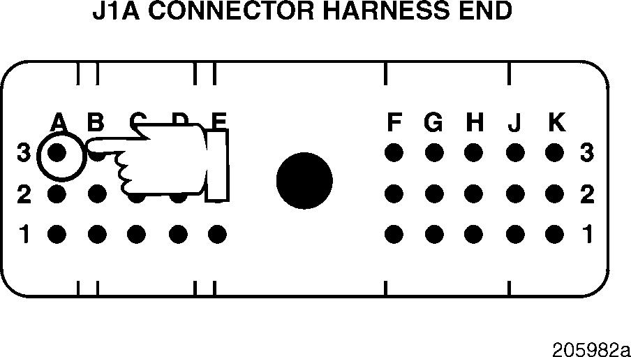
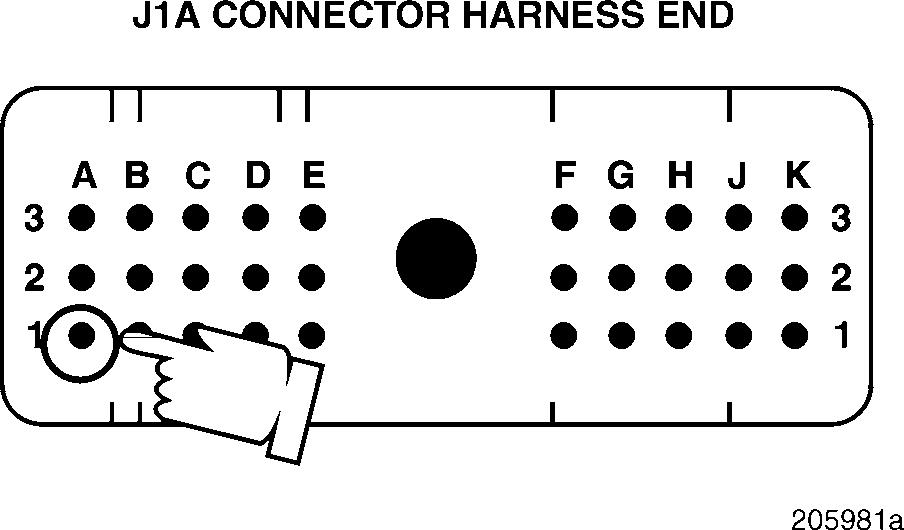
1.Connect a jumper between J1A connector pins A3 and A1.
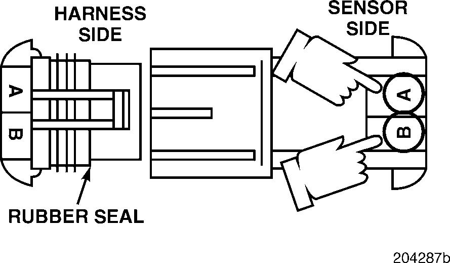
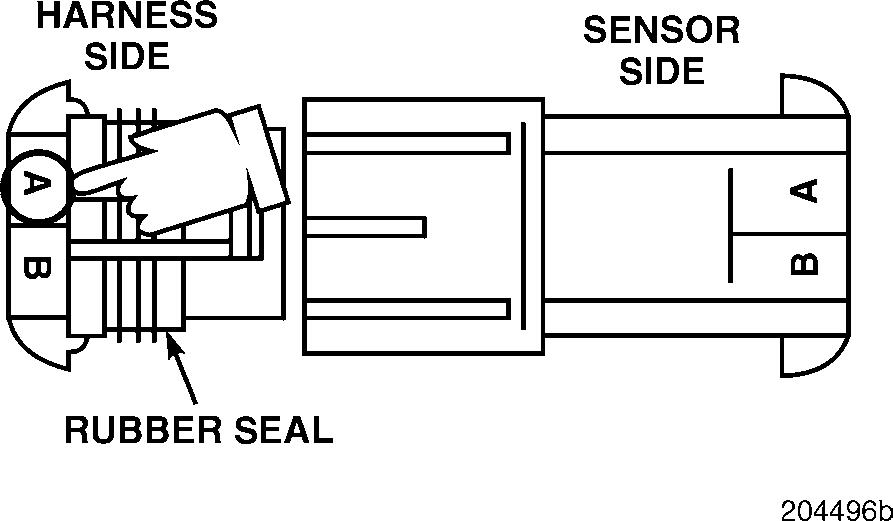
2.Check for continuity between harness connector pins A (the signal [+] line) and B (the ground [ ] line), on the solenoid end of the harness.
If there is continuity, proceed to Test 32.
If there is no continuity, proceed to Test 33.
DIAGNOSTIC CODE 3-5 (ELECTRICAL)
Test 32
Checking for an open on the solenoid end of the harness
Test 33
Checking for an open in the timing solenoid PLUS (+) line on the module end of the harness
1.Remove the jumper between J1A connector
2.Reconnect the timing solenoid to the harness.
3.Measure the resistance between J1A connector pins A1 (the timing solenoid PLUS [+] line) and A3 (the timing solenoid MINUS [ ] line).
If the resistance is between 1 and 3 ohms, proceed to Test 64.
If the resistance is not between 1 and 3 ohms, the timing solenoid PLUS [+] or MINUS [ ] lines are open or faulty at the connector. Repair the connector if possible. Otherwise, replace the solenoid. Retest to be sure the problem has been corrected
1.Connect a jumper between J1A connector
A1 and J1B connector pin P2.
2.Check for continuity from harness connector pin A (the signal [+] line), on the sensor side of the connector, to a good ground.
If there is continuity, repair the open in the timing solenoid MINUS [ ] line (pin A3). Retest to be sure the problem has been corrected
If there is no continuity, select another chassis ground. If there is still no continuity, repair the timing solenoid PLUS [+] line (pin A1). Retest to be sure the problem has been corrected.


