1 minute read
DIAGNOSTIC CODE 4-1, 4-2 OR 4-3


Test 4
Checking for a short in the sensor
1.Turn the ignition key to the OFF position.
2.Disconnect the J1A connector from the V-MAC II module.
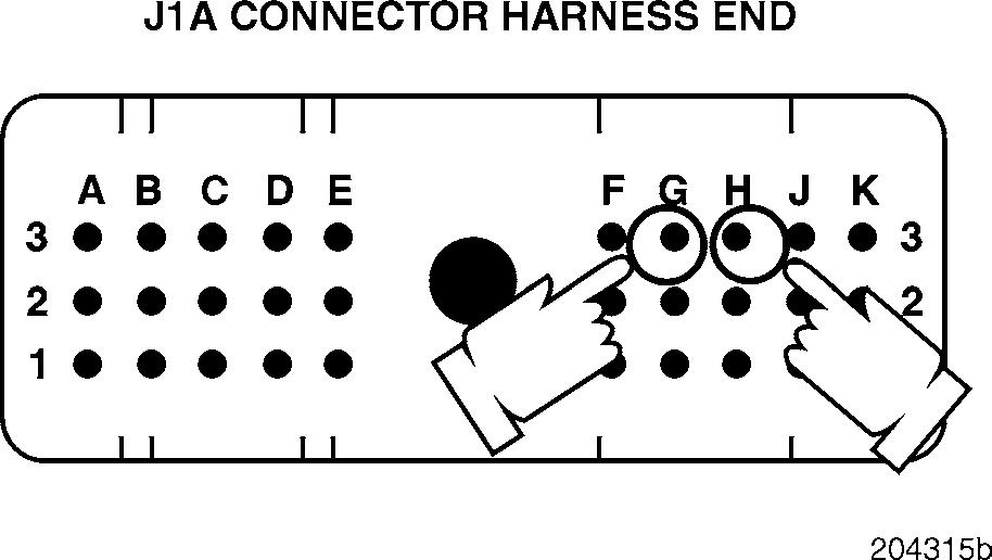
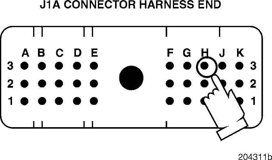
3.Check for continuity between J1A connector pins H3 (the MPH sensor PLUS [+] line) and G3 (the MPH sensor MINUS [ ] line).
If there is continuity, locate and repair the short in the harness. Retest to be sure the problem has been corrected.
If there is no continuity, proceed to Test 10.
Test 6
Checking the voltage in the harness
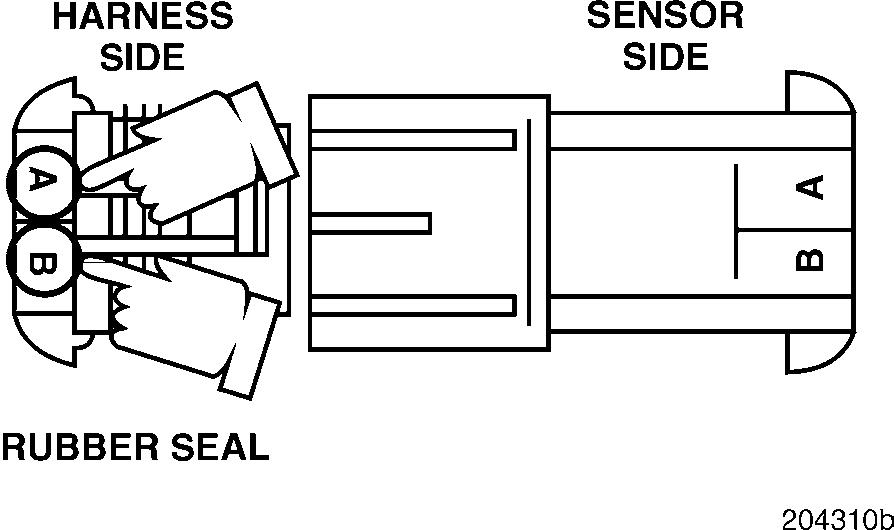
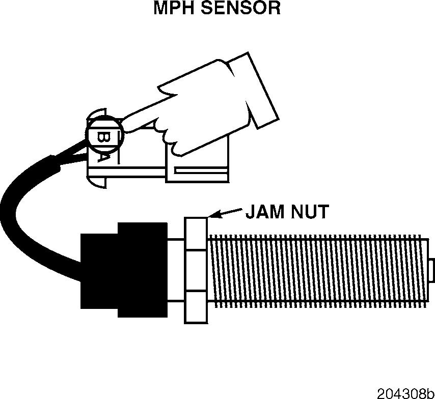
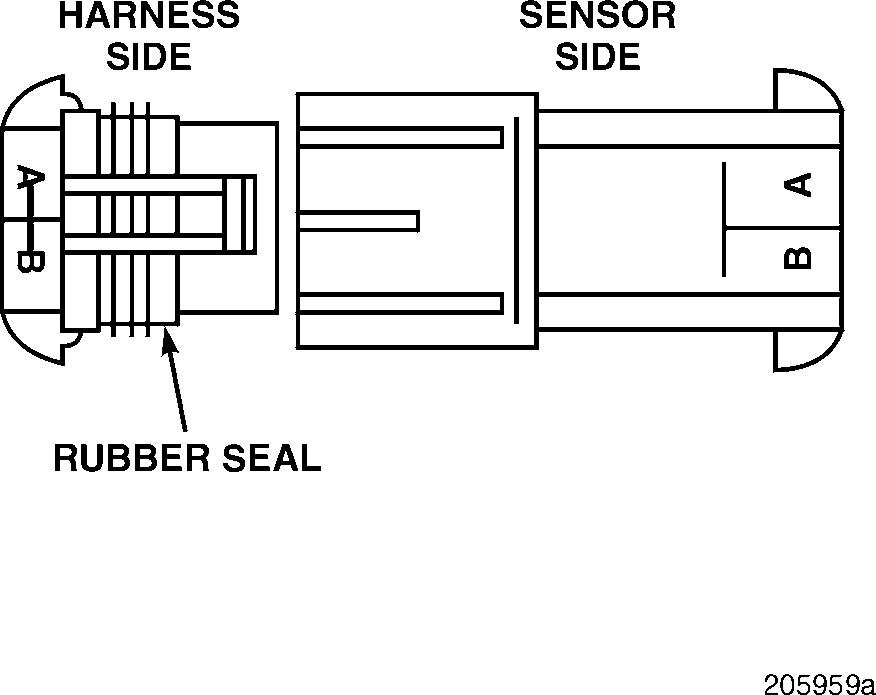
1.Visually inspect the MPH sensor for a repairable short to ground on harness connector pin B.
If there is a repairable condition, repair the connector or replace the MPH sensor. Retest to be sure the problem has been corrected.
If there is not a repairable condition, replace the MPH sensor. Retest to be sure the problem has been corrected.
Test 5
Checking for continuity on the MPH PLUS (+) and MPH MINUS ( ) lines
1.Turn the ignition key to the ON position.
2.Measure the voltage between harness connector pins A (the signal [+] line) and B (the ground [ ] line) on the sensor side of the connector.
If the voltage is greater than 4.0 volts, proceed to Test 13.
If there is no voltage, proceed to Test 12.
DIAGNOSTIC CODE 4-1, 4-2 OR 4-3
Test 10
Checking for continuity in the harness
Test 12
Checking for continuity in the harness
1.Check
If there is continuity, locate and repair the short in the harness. Retest to be sure the problem has been corrected.
If there is no continuity, proceed to Test 20.
1.Turn the ignition key to the OFF position.
2.Connect a jumper between harness connector pins A and B, on the harness end of the connector.
3.Disconnect the J1A connector from the V-MAC II module.
4.Check for continuity between J1A connector pins H3 (the MPH sensor PLUS [+] line) and G3 (the MPH sensor MINUS [ ] line).
If there is continuity, proceed to Test 24.
If there is no continuity, proceed to Test 25.


