6 minute read
SYMPTOM RELATED DIAGNOSTICS


SWITCH CIRCUIT FAILURE (continued)
Test 34
Checking for proper switch operation
1.Turn the ignition key to the OFF position.
2.Turn the switch ON.
3.Check for continuity across the two leads of the switch.
If there is continuity, proceed to Test 69.
If there is no continuity, replace the switch. Retest to be sure the problem has been corrected.
Test 69
Checking for a short to ground
1.Disconnect the remaining V-MAC II module connectors.
2.Check for continuity between the switch signal pin and each of the other pins (one at a time) on the J1A, J1B and J2 connectors, and also a good ground.
If there is continuity with another pin or ground, locate and repair the short in the harness. Retest to be sure the problem has been corrected.
If there is no continuity, proceed to Test 138.
Test 138
Checking for a short to ground in the switch
1.With the ignition key in the OFF position, check for continuity from either pin on the switch to a good ground. Turn the switch ON and OFF.
If at any time there is continuity between the switch and ground, replace the switch. Retest to be sure the problem has been corrected.
If there is no continuity with ground, there is a break in the wire which supplies the switch signal to V-MAC II. Repair or replace the wire. Retest to be sure the problem has been corrected.
Symptom Related Diagnostics
Symptom Related Troubleshooting Chart
Problem
Unable to set cruise/speed control with lights ON (turn signals, headlights).
Additional SymptomsPossible Failure
Speed control can be reset once lights are turned ON, but not turn signals.
Service Hints
Able to set cruise/speed control but it disengages intermittently.
Cruise automatically resumes itself.
GENERAL: Continuity between J2 connector pins B2 or B3 (service and parking brake lines) and the lighting circuit.
Front directional lamp ground.
Tractor or trailer ground connections.
Faulty directional switch operation.
Tractor or trailer rear directional lamp ground.
Clutch switch adjustment. Intermittent short (closed contact) in clutch switch. Intermittent short to voltage after clutch switch engaged line (J2-C1).
First watch tractor tail/stop lamps. Turn on the lights in question and see if the lamps turn ON. If they do not turn ON, or turn ON dimly, repair the lamps.
If the lamps work properly: Monitor the service and parking brake switch status on the PC or Pro-Link. Watch the status as you turn the various lamps ON and OFF. The status should not change.
Check clutch switch adjustment.
If adjustment is OK: Disconnect wire J2-C1 from switch leading to the module. If the problem continues, the wire is shorted to voltage. If the problem is fixed, the clutch switch is defective.
Must press RESUME switch to reactivate cruise, no faults.
Faulty service brake switch
Faulty park brake switch. Intermittent short to voltage after brake switch engaged line (J2-B2 or B3).
Monitor the service and parking brake switch status on the PC or Pro-Link. Watch the status while driving in cruise.
Alternate: set up the customer definable data log to record service brake and park brake application while in cruise mode. This may be more effective if the problem occurs infrequently. The driver must be instructed to NOT use the service brake while in cruise but to disengage with the ON/OFF switch.
Fault 7-1 (Service Brake) becomes active. Must press service brake and then RESUME to re-engage cruise.
Speedometer erratic.
Open, short to ground or short to voltage on MPH (+) and MPH ( ) lines (J1A-H3 or G3).
Misadjusted MPH sensor.
If the driver reports that cruise dropped out by itself (without application of the service brake) there is nothing wrong with the service brake, despite the fault. Shorts and opens on the MPH signal will appear as a sudden deceleration, causing cruise to disengage and the fault to be logged.
Symptom Related Diagnostics
SYMPTOM RELATED TROUBLESHOOTING CHART (continued)
Poor performance: Continuous N/AVerify adequate fuel and air supply.
Reduced engine speed or reduced high idle speed.
Check filters, hoses, charge air cooler, etc.
Reduced high idle.
Throttle unresponsive around low idle with light loads. May not be able to achieve 100% throttle on the PC or Pro-Link display.
Customer’s high idle setting is lower than the driver is used to.
Lower gear road speed limit or road speed limit is lower than the driver is used to.
Throttle pedal reference line (J1B-L2) should be 5 volts.
Intermittent problems: Poor connection at the module or pedal. Faulty pedal.
Poor module ground connection or throttle ground line (J1B-L2).
Determine high idle, road speed limit and lower gear road speed limits using the PC or Pro-Link. If these are the cause of the complaint, educate the driver to the set up that his fleet has specified.
Examine the % throttle with the PC or Pro-Link.
Page 215
Symptom Related Diagnostics
SYMPTOM RELATED TROUBLESHOOTING CHART (continued)
Poor performance: Engine stumbles then regains power while driving.
Runs rough under throttle pedal control.
Does not occur in cruise or speed control unless the throttle pedal is applied.
Engine brake activates when the engine stumbles (if equipped and turned ON).
Intermittent problems:
Throttle pedal reference line (J1B-L2) intermittent open or short to voltage.
Throttle pedal signal line (J1B-L1) intermittent open, short to voltage or short to ground.
Throttle pedal ground line (J1B-L3) intermittent open or short to voltage.
Intermittent bad module ground.
Faulty throttle pedal.
Examine the % throttle pedal with the PC or Pro-Link. Use enhanced diagnostics mode of the PC or Pro-Link if fault codes are not present.
Runs rough all of the time, under throttle pedal control, cruise control and speed control.
When out of gear, the engine speed jumps up or down.
Engine brake activates when the engine stumbles (if equipped and turned ON).
Tachometer needle agrees fairly well with engine speed.
Loose injection pump connector.
Intermittent problems:
Rack actuator (+) line (J1AH1) is open, shorted to voltage or shorted to ground.
Rack position (+) line (J1AK1 or K2) is open, shorted to ground or shorted to voltage.
Rack position (+) line (J1AJ3) is open or shorted to voltage.
Ensure that the injection pump connector ring is locked.
If the problem only occurs when the engine is hot, pour 2–3 gallons of water on the injection pump cover when the engine stumbles. If the engine runs smoothly for a period of time, the problem may be a bad connection inside the injection pump. Send the pump to a certified pump repair shop for repair.
Check the inactive fault table for rack actuator and rack position sensor faults.
Rack actuator (+) lines (J1AB1 and B2) and rack actuator ( ) lines (J1A-A2 and B3) have splices in the harness near the module. If these splices should break, there may be an intermittent open in the lines.
Similar to description above, except that the tachometer needle jumps wildly when the engine stumbles, even when the truck is in gear and the engine speed is steady.
Injection timing is erratic when the engine stumbles.
Similar to the description above, with the tachometer needle following the engine speed.
Accessory relay is sometimes heard when engine stumbles.
Intermittent problems:
RPM/TDC (+) line (J1A-H1) is open, shorted to voltage or shorted to ground.
RPM/TDC ( ) line (J1A-H2) is open or shorted to voltage.
Misadjusted RPM/TDC sensor.
Faulty accessory relay. Faulty key switch.
Disconnect the RPM/TDC sensor and run the engine. The stumble should disappear if this is the problem.
Use the enhanced diagnostics mode of the PC or Pro-Link if fault codes are not present to find the source of the problem.
Use the standard log from the INFOMAX PC program to count key cycles while the problem occurs.
Symptom Related Diagnostics
SYMPTOM RELATED TROUBLESHOOTING CHART (continued)
Poor performance: Engine speed rolls, particularly at low idle.
Increased low idle speed: Continuous. Cannot reach 0% throttle (this is not always evident with this failure.
Possible misadjusted injection pump control rod. Refer to the instructions for diagnostic blink codes 5-4 in this manual for proper adjustment procedures.
Broken throttle pedal springs. High throttle pedal reference voltage in excess of 5.25 volts (J1B-L2). Continuity between pin J1B-L1 and other wires. Poor module ground.
Engine will not start. No fuel or fuel pressure to injection pump. No power to the V-MAC II module.
Low battery voltage. Loose injection pump connector.
Misadjusted RPM/TDC sensor AND starter input (+) line (J2-A3) is open.
If a new pump has been installed, make sure the pump is primed. Push on the hand primer until resistance is felt.
Use the standard log from the INFOMAX PC program to count starter engagements, or use the switch status screen on the PC or Pro-Link to monitor the starter (Auxiliary No. 3 switch).
Apply 100% throttle when cranking. Even if the sensor is misadjusted and the starter input is broken, the engine should engage.
Engine shuts down, accessories turn OFF with the key in the ON position.
Co-Pilot requests a code, or some other alarm is ON.
Module is in a theft deterrence or forced shutdown mode.
Check on the theft deterrence or forced shutdown status with the PC or Pro-Link, or check with the customer.
Idle shutdown. Engine protection shutdown. Verify that the engine has not shut down due to an engine protection shut down (low oil pressure, high coolant temperature, low coolant level).
Page 217
Repair And Adjustment Procedures
Connector Repair
Deutsch Connectors
The 31 or 23-pin bulkhead connector and the serial communication port connector are Deutsch connectors. To remove and replace terminals, follow the instructions listed in this section.
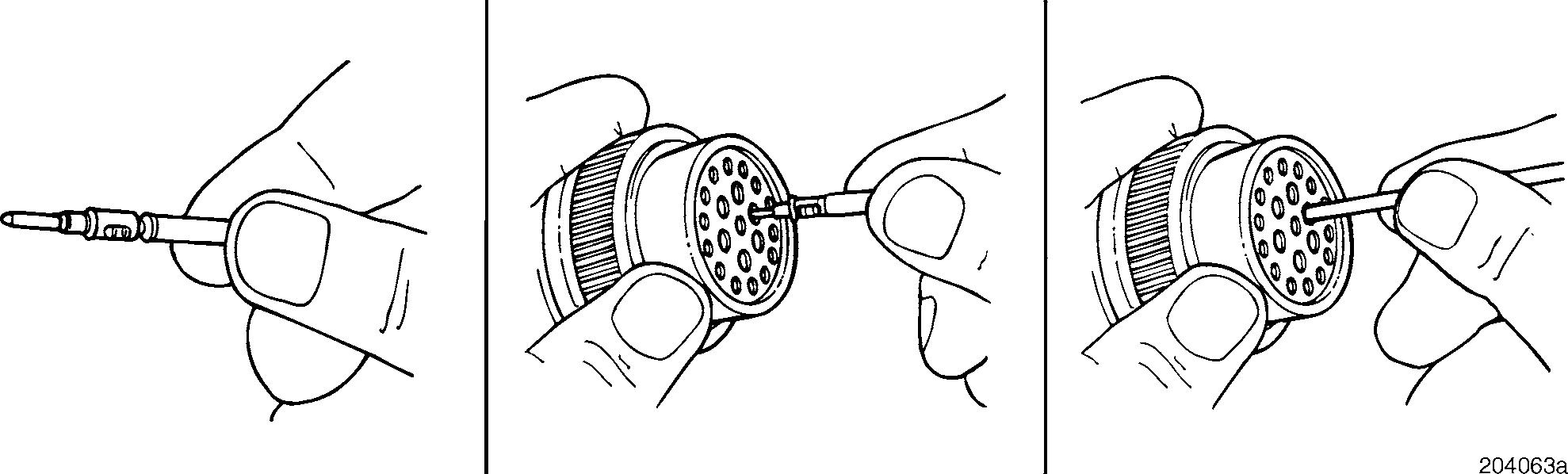
Contact Insertion
1.Grasp the contact approximately 1 inch (25.4 mm) behind the contact crimp barrel.
2.Hold the connector with the rear grommet facing you.
3.Push the contact straight into the connector grommet until a positive stop is felt. A slight tug will confirm that it is properly locked in place.


