2 minute read
DIAGNOSTIC CODE 3-5 (ADVANCED)


When performing electrical tests, it is important to wiggle wires and connectors to identify intermittent connection problems.
Blink Code 3-5
PID
SID 2
FMI 7
MID 142
Name Timing Actuator
Failure Mechanical system not responding
This fault is only active above a specific engine speed and load. It may be inactive by the time the truck reaches the service shop.
Test 1
Checking timing at low idle
Follow the instructions in Tests 2 through 72, running the engine at low idle. Proceed to Test 2.
Test 2
Checking dynamic timing
1.Turn the ignition key to the OFF position.
2.Connect the V-MAC II module connectors.
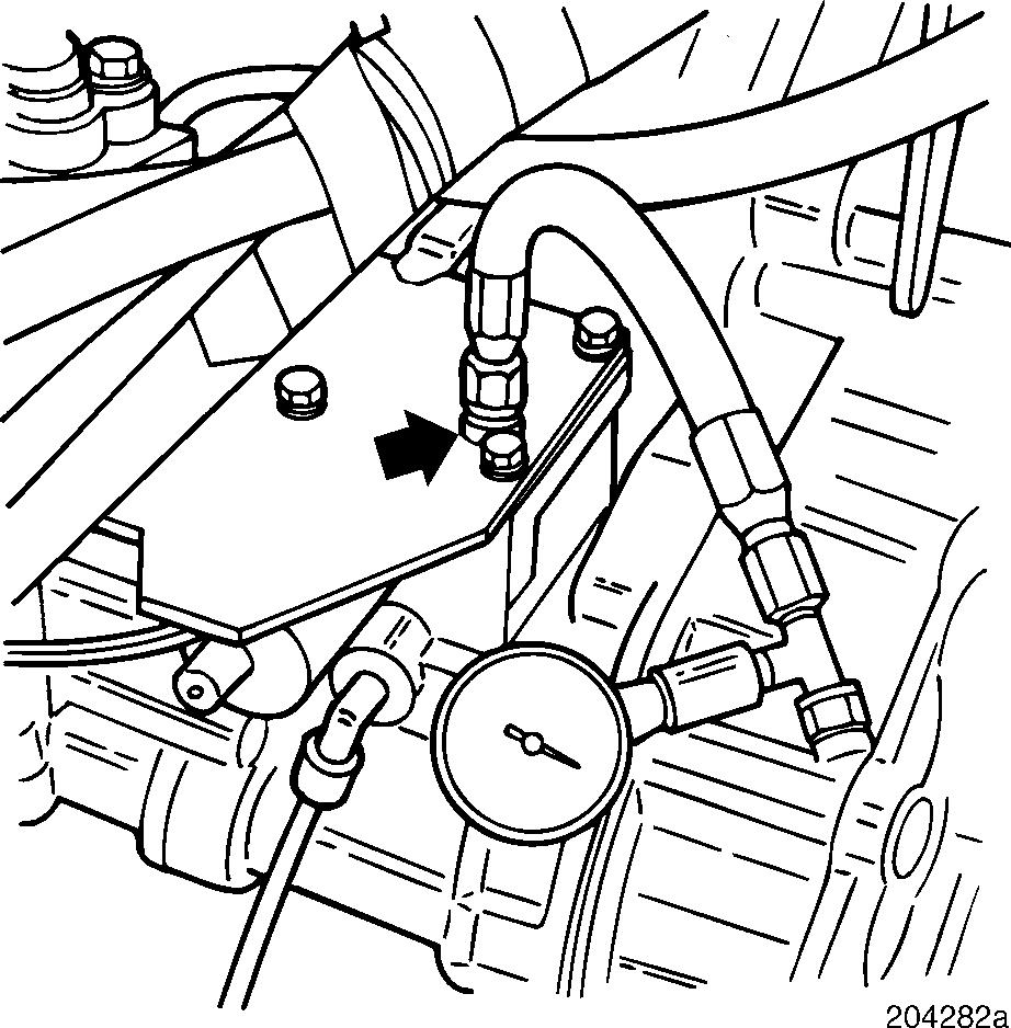
3.Connect a pressure gauge to the diagnostic port.
4.Disconnect the timing valve connector from the wiring harness.
5.Connect a jumper between the two connector halves, using one set of terminals. For example, connect the A terminals (jumper from terminal A on the harness side to terminal A on the sensor side). On the other terminals, use two jumpers to connect the circuit through a digital multimeter set to measure current (AMPS) on the 10A scale.
6.Start the engine.
7.Record the low or high idle timing, the diagnostic port pressure, and the timing valve current. Reconnect the timing valve to the harness when completed.
If the timing status shows the timing is too advanced (diagnostic tool displays “++”), proceed to Test 5.
Otherwise, proceed to Test 4.
Test 4
Checking for retarded timing
If the timing status shows the timing is too retarded (diagnostic tool displays “--”), proceed to Test 9.
Otherwise, proceed to Test 8.
Page 97
DIAGNOSTIC CODE 3-5 (ADVANCED)
Test 5
Timing is too advanced. Checking diagnostic port pressure
Test 9
Timing is too retarded. Checking diagnostic port pressure
If the pressure in the diagnostic port is much less than the gallery pressure, proceed to Test 18.
If the pressure in the diagnostic port is about equal to the gallery pressure, the ECONOVANCE is stuck. Repair or replace the ECONOVANCE. Retest to be sure the problem has been corrected.
Test 10
Checking current to the timing control valve
If the current to the timing control valve is greater than 0.9 amps, proceed to Test 20.
If the current to the timing control valve is less than 0.9 amps, proceed to Test 21.
Test 11
If the pressure in the diagnostic port is greater than 0 psi (there is some pressure), proceed to Test 10.
If the pressure in the diagnostic port is 0 psi, proceed to Test 11.
Test 8
Checking timing at high idle
If you just ran Test 4 at low idle, repeat Tests 2 through 72, running the engine at high idle. Proceed to Test 2.
If you just ran Test 4 at high idle, proceed to Test 16.
Checking the RPM/TDC sensor
1.Disconnect the timing valve connector from the wiring harness.
2.Record the timings at low idle and high idle.
If the high idle timing is greater than the low idle timing, replace the RPM/TDC sensor. Retest to be sure the problem has been corrected.
If the high idle timing is less than or equal to the low idle timing, proceed to Test 23.


