2 minute read
REPAIR AND ADJUSTMENT PROCEDURES


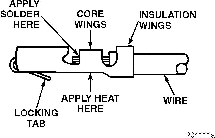
4.Inspect the terminal for a good solder application.
Connector bodies are keyed for proper mating of contacts. Be sure that the contacts are aligned properly.
Before inserting the contacts, carefully spread the locking tabs to ensure a good lock in the connector body.
When replacing contacts, except those on a Deutsch connector, they must all be soldered after crimping.
After making any repairs to connectors, make sure that all rubber seals are properly positioned on the connectors before reconnecting them.
Page 227
Repair And Adjustment Procedures
Clutch Switch Adjustment
For proper operation of the engine brake and speed control functions, the clutch switch must be adjusted and working properly. The clutch switch is located under the dash, near the top of the clutch pedal assembly. This switch is a “normally open” switch. However, when used with a V-MAC II system, it is set to be closed during normal operation and opens only when the clutch pedal is depressed.
Two mounting screws hold this switch in place. Loosening the two screws makes it possible to move the switch slightly, to permit adjustment. Make sure that the clutch switch is closed when the clutch pedal is in the fully released (not depressed) position, and open when the clutch pedal is depressed. Be sure to adjust the switch to allow approximately 1/2 inch of clutch free play travel before the switch opens.
Sensor Adjustment
RPM/TDC Sensor
1.Turn the sensor in by hand until it bottoms against the flywheel.
2.Back out exactly 1 turn.
3.Torque the jam nut to 15 lb-ft (20 N•m).
MPH Sensor
1.Turn the sensor in by hand until it bottoms against the speedometer tone wheel.
2.Back out exactly 1 turn.
3.Torque the jam nut to 15 lb-ft (20 N•m).
TEM Sensor
1.Coat the sensor thread with Silastic.
2.Turn in by hand until it bottoms in the housing.
3.Torque the jam nut to 22 lb-ft (30 N•m).
Resetting Low Idle Speed
This section explains the procedure for resetting low idle speed using the speed control switches.
The V-MAC II system allows the low idle to be set within the range of 500 to 750 rpm. This range of flexibility allows the operator to set the low idle to the smoothest possible engine speed for the vehicle.
Resetting the low idle speed involves two steps:
1.Place V-MAC II in the “low idle adjust” mode (so that V-MAC can accept the new low idle speed).
2.Set the new idle speed.
Completing the first step in the process requires the following: r The V-MAC II module must have the Low IdleAdjust option enabled in using Customer Data Programming software. r There must be no active faults in the system. r The vehicle must be stationary. r The parking brake must be applied. r The throttle pedal must be at the idle position (not depressed). r The speed control ON/OFF switch must be turned ON and OFF 3 times within 2 seconds. At this point, the idle speed will drop to 500 rpm — V-MAC II is now ready to accept a new speed. Be sure to leave the switch in the ON position.
The PTO minimum engine speed in Customer Data should be set at 475 rpm. Otherwise, the low idle speed can be adjusted only by using a diagnostic tool (Pro-Link or PC).


