12 minute read
DIAGNOSTIC TOOLS & PROCEDURES


Engine Shutdown
If the engine shuts down, check the following before calling for service.
r Is the electronic fault lamp on? If so, determine the blink code and call for service.
r Is the engine shutdown lamp on after the engine has shut down? If so, the coolant level is low or the coolant temperature is too high.
r Does the engine start? If so, the shutdown was probably due to Idle Shutdown. If the engine shutdown lamp comes on, check for low oil pressure. If the oil pressure is low, TURN OFF THE ENGINE IMMEDIATELY!
r If the engine does not start, check for low fuel level.
DIAGNOSTIC CODE 1-1 OR 1-2
DIAGNOSTIC BLINK CODE 1-1 OR 1-2
ENGINE OIL PRESSURE SENSOR TESTS
When performing electrical tests, it is important to wiggle wires and connectors to identify intermittent connection problems.
Blink Code 1-11-2
PID 100 100
SID
FMI 43
MID 142 142
Name Engine Oil Pressure Engine Oil Pressure
Voltage above normal or shorted high
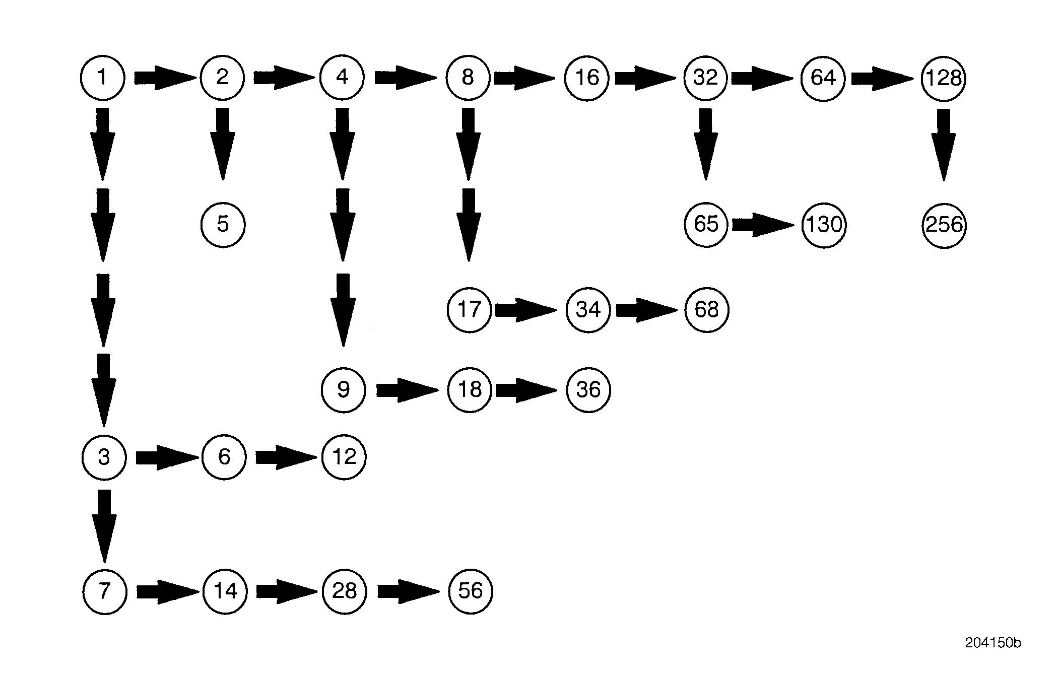
Test 1
DIAGNOSTIC CODE 1-1 OR 1-2
Checking for proper voltage on the voltage reference (+) line
Test 2
Checking for voltage on the ground ( ) line
1.Disconnect the harness from the oil pressure sensor.
2.Turn the ignition key to the ON position.
3.Measure the voltage from harness connector pin B (the voltage reference [+] line) to a good ground.
If the voltage is between 4.75 and 5.25 volts, proceed to Test 2.
If the voltage is not between 4.75 and 5.25 volts, proceed to Test 3.
1.Measure the
If the voltage is greater than 0.5 volts, proceed to Test 5.
If the voltage is less than 0.5 volts, proceed to Test 4.
Test 3
Checking the voltage reference (+) line, high or low
If the voltage in Test 1 was greater than 5.25 volts, proceed to Test 6.
If the voltage in Test 1 was less than 4.75 volts, proceed to Test 7.
Test 4
DIAGNOSTIC CODE 1-1 OR 1-2
Checking for stray voltage on the signal (+) line
Test 5
Checking for voltage in the harness on the sensor ground ( ) line
1.Measure the voltage from to a good ground.
If voltage is greater than 0.5 volts, proceed to Test 9.
If the voltage is less than 0.5 volts, proceed to Test 8.
1.Turn
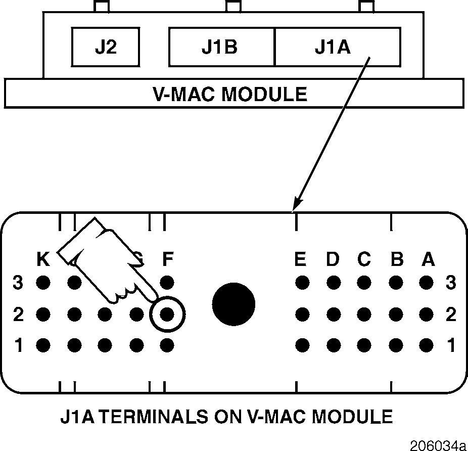
2.Disconnect the J1A and J1B connectors from the V-MAC II module.


3.Connect the serial link jumper into the serial communication port.
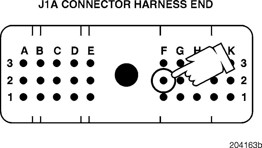
4.Measure the voltage from J1A connector pin G2 (the sensor ground [ ] line) to a good ground.
If the voltage is greater than 0.5 volts, locate and repair the short on the sensor ground (−) line in the harness. Replace the V-MAC II module and the oil pressure sensor. Retest to be sure the problem has been corrected.
If the voltage is less than 0.5 volts, replace the V-MAC II module and the oil pressure sensor. Retest to be sure the problem has been corrected.
Test 6
DIAGNOSTIC CODE 1-1 OR 1-2
Checking for stray voltage in the sensor power (+) line
Test 7
Checking for continuity in the harness
1.Turn the ignition key to the OFF position.
2.Disconnect the J1A and J1B connectors from the V-MAC II module.

3.Connect the serial link jumper into the serial communication port.
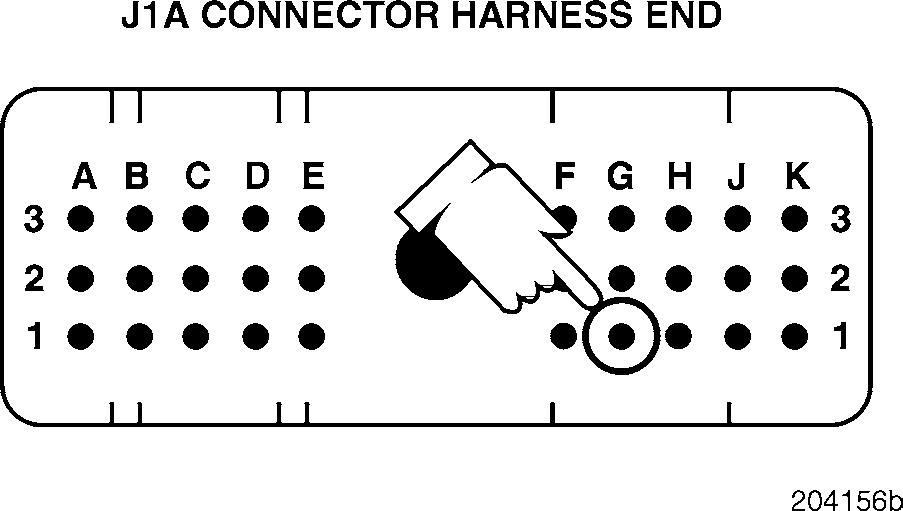
4.Measure the voltage from J1A connector pin G1 (the sensor power [+] line) to a good ground.
If the voltage is greater than 5 volts, locate and repair the short to power. Replace the oil pressure sensor. Retest to be sure the problem has been corrected.
If the voltage is less than 5 volts, proceed to Test 12.
1.Turn the ignition key to the OFF position.
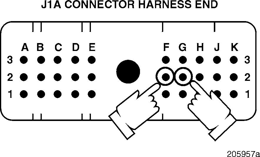
2.Connect a jumper between harness connector pins B and C.
3.Disconnect the J1A connector from the V-MAC II module.
4.Check for continuity between J1A connector pins G1 (the sensor power [+] line) and F2 (the oil pressure signal [+] line).
If there is continuity, proceed to Test 14.
If there is no continuity, locate and repair the open in the sensor power [+] line (pin G1). Retest to be sure the problem has been corrected.
Test 8
DIAGNOSTIC CODE 1-1 OR 1-2
Checking for a shorted signal to ground in the harness
3.Connect the serial link jumper into the serial communication port.
4.Measure the voltage from J1A connector pin F2 (the oil pressure signal [+] line) to a good ground.
If the voltage is greater than 0.5 volts, locate and repair the short to power in the oil pressure signal [+] line. Retest to be sure the problem has been corrected.
If the voltage is less than 0.5 volts, proceed to Test 18.
Test 12
Checking for a pin-to-pin short
1.Turn the ignition key to the OFF position.
2.Check for continuity from harness connector pin C (the signal [+] line) to a good ground.
If there is continuity, proceed to Test 17.
If there is no continuity, proceed to Test 16.
Test 9
Checking the harness for stray voltage
1.Disconnect the serial link jumper.
2.Visually inspect the J1A connector, on the module end, for a pin-to-pin short around pin G1.

If there is a repairable short, repair the short to power in the J1A connector. Replace the oil pressure sensor. Retest to be sure the problem has been corrected.
1.Turn the ignition key to the OFF position.
2.Disconnect
If there is not a repairable short, replace the V-MAC II module and the oil pressure sensor. Retest to be sure the problem has been corrected.
Test 14
Checking for a short to ground in the sensor power (+) line
Test 16
Checking for an open in the signal line in the harness
1.Turn the ignition key to the OFF position.
2.Check for continuity from J1A connector pin
(the sensor power [+] line) to a good ground.
If there is continuity, locate and repair the short to ground in the voltage reference (+) line in the harness or connector. Retest to be sure the problem has been corrected.
If there is no continuity, proceed to Test 28.
1.Turn the ignition key to the OFF position.
2.Connect a jumper between harness connector pins B and C.
3.Disconnect the J1A connector from the V-MAC II module.
4.Check for continuity between J1A connector pins G1 (the sensor power [+] line) and F2 (the oil pressure signal [+] line).
If there is continuity, disconnect the jumper and proceed to Test 32.
If there is no continuity, locate and repair the open in the oil pressure signal [+] line in the harness or connectors. Retest to be sure the problem has been corrected.
Test 17
DIAGNOSTIC CODE 1-1 OR 1-2
Checking for continuity to ground on the oil pressure signal line
3.Check for continuity between J1A connector pin F2 (the oil pressure signal [+] line) and each of the other pins (one at a time) on the J1A, J1B and J2 connectors.
If there is continuity with another pin, locate and repair the short in the oil pressure signal [+] line. Retest to be sure the problem has been corrected.
If there is no continuity, proceed to Test 36.
Test 28
Checking for a pin-to-pin short in the harness
1.Turn the ignition key to the OFF position.
2.Disconnect the J1A connector from the V-MAC II module.
3.Check for continuity from J1A connector pin F2 (the oil pressure signal [+] line) to a good ground.
If there is continuity, locate and repair the short to ground in the oil pressure signal [+] line. Retest to be sure the problem has been corrected.
If there is no continuity, proceed to Test 34.
Test 18
Checking for a pin-to-pin short in the harness
1.Turn the ignition key to the OFF position.
2.Remove the jumper between pins B and C.
3.Disconnect the J1B and J2 connectors from the V-MAC II module.
4.Check for continuity between J1A connector pin G1 (the sensor power [+] line) and each of the other pins (one at a time) on the J1A, J1B and J2 connectors.
If there is continuity with another pin, locate and repair the short to ground in the sensor power [+] line in the harness or connector. Retest to be sure the problem has been corrected.
If there is no continuity, proceed to Test 56.
1.Disconnect the serial link jumper.
2.Disconnect the J2 connector from the V-MAC
Test 32
DIAGNOSTIC CODE 1-1 OR 1-2
Checking continuity from the ground ( ) line to ground
Test 34
Checking for a pin-to-pin short in the harness
1.Turn the ignition key to the OFF position.
2.Connect the J1A connector to the V-MAC II module.
3.Check for continuity from harness connector pin A (the ground [ ] line) to a good ground.
If there is continuity, proceed to Test 64. If there is no continuity, proceed to Test 65.
1.Turn the ignition key to the OFF position.
2.Disconnect the J1B and J2 connectors from the V-MAC II module.
3.Check for continuity between J1A connector pin F2 (the oil pressure signal [+] line) and each of the other pins (one at a time) on the J1A, J1B and J2 connectors.
If there is continuity with another pin, locate and repair the short in the oil pressure signal [+] line. Retest to be sure the problem has been corrected.
If there is no continuity, proceed to Test 68.
Test 36
DIAGNOSTIC CODE 1-1 OR 1-2
Checking for a pin-to-pin short at the V-MAC II module connector
Test 56
Checking for an open or short at the V-MAC II
1.Visually inspect the module side of the J1A connector for a repairable short between pin F2 (the oil pressure signal [+] line) and any other pin.
If there is a repairable condition, repair the short between the pins. Retest to be sure the problem has been corrected.
If there is not a repairable condition, the V-MAC II module is damaged. The sensor may also be damaged if the failure was the result of the ground line being shorted to voltage. Replace both the V-MAC II module and the oil pressure sensor. Retest to be sure the problem has been corrected.
1.Visually inspect the module side of the J1A connector for an open or short around pin G1 (the sensor power [+] line).
If there is a repairable condition, repair the short or open on the J1A connector. Retest to be sure the problem has been corrected.
If there is not a repairable condition, reconnect the V-MAC II harnesses and the oil pressure sensor connector. Turn the ignition key to the ON position. If blink code 1-1 is still active, replace the V-MAC II module. If the fault is not active, check for loose connections at the sensor and module connectors. Retest to be sure the problem has been corrected.
Test 64
DIAGNOSTIC CODE 1-1 OR 1-2
Checking for an open in the V-MAC II module
Test 65
Checking for an open in the sensor ground ( ) line
1.Connect a jumper between harness connector pins B and C.
2.Turn the ignition key to the ON position.
If the active fault changes from voltage low (code 1-1) to voltage high (code 1-2), proceed to Test 128.
If the active fault does not change, turn the ignition key to the OFF position. Check the V-MAC II module connectors for dirt which could cause a short to ground. Repair the short or replace the V-MAC II module. Retest to be sure the problem has been corrected.
1.Connect a jumper between harness connector pins A and C.
2.Disconnect the J1A connector from the V-MAC II module.
3.Check for continuity between J1A connector pins F2 (the oil pressure signal [+] line) and G2 (the sensor ground [ ] line).
If there is continuity, proceed to Test 130.
If there is no continuity, locate and repair the open in the sensor ground (−) line. This open may be in the harness or connector. Retest to be sure the problem has been corrected.

Test 68
DIAGNOSTIC CODE 1-1 OR 1-2
Checking for a repairable short at the V-MAC II module
Test 128
Checking for a fault in the sensor connector
1.Visually inspect the module end of the J1A connector for a short between pin F2 (the oil pressure signal [+] line) and all adjacent pins.
If there is a repairable short, repair the short at the connector on the oil pressure signal [+] line. Retest to be sure the problem has been corrected.
If there is not a repairable short, replace the V-MAC II module. Retest to be sure the problem has been corrected.
It is good practice to be sure the test leads in your electrical test kit are in good condition (not bent or damaged in any way).
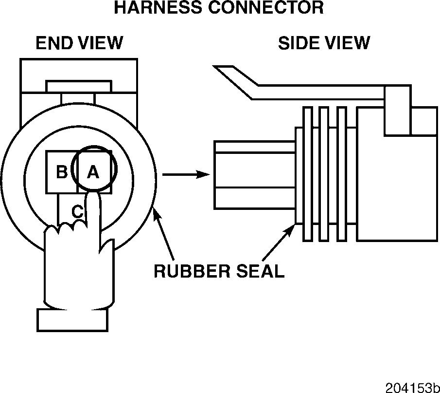
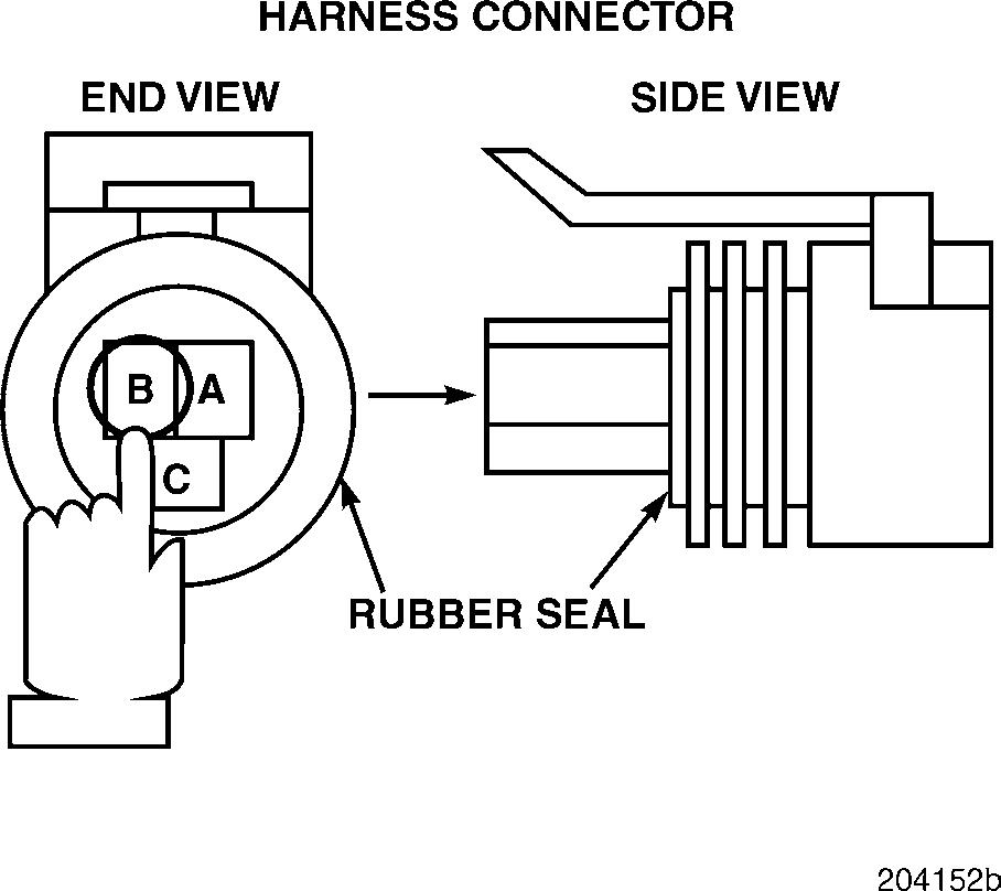
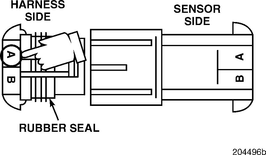
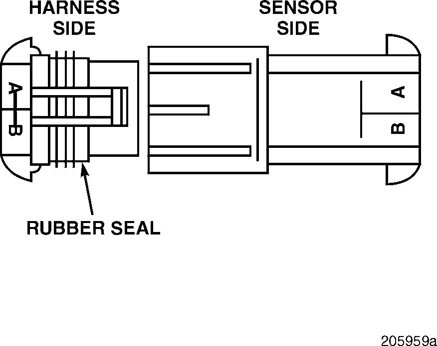
Figure 43 — Inspect Both Sides of Sensor for an Open

1.Visually inspect both sides of the sensor connector for a repairable open in any of the pins.
If there is a repairable open, repair or replace the oil pressure sensor connector. Retest to be sure the problem has been corrected.
If there is not a repairable open, continue with the next step.
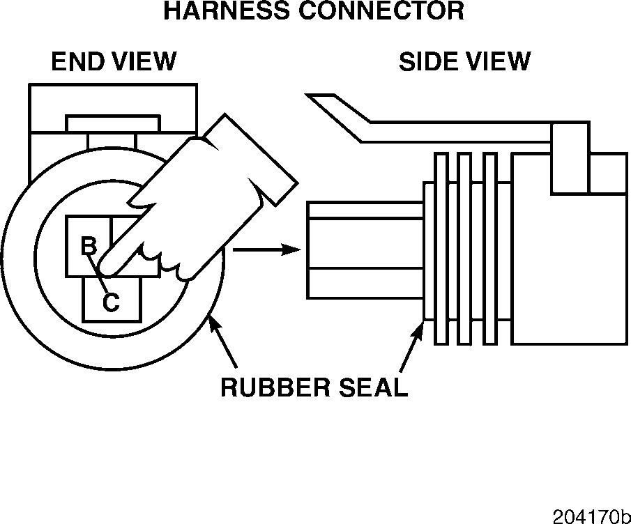
2.Find the gray J 35616-2 male test lead from the J 38581 V-MAC jumper wire kit. Align the male test lead with one of the rectangular female pins in the sensor connector. Gently push the test lead into the sensor connector pin. Repeat this process for the remaining two female pins, being careful to align the lead with the rectangular pins (pin C is turned 90 degrees from pins A and B).
If any of the pins in the connector feel loose, repair or replace the connector. Retest to be sure the problem has been corrected.
If none of the pins in the connector feel loose, continue with the next step.
DIAGNOSTIC CODE 1-1 OR 1-2
3.Find the gray J 35616-3 female test lead from the J 38581 V-MAC jumper wire kit. Align the female test lead with one of the rectangular male pins in the oil pressure sensor. Gently push the test lead over the pin. Repeat this procedure for the remaining two male pins, being careful to align the lead with the rectangular pins (pin C is turned 90 degrees from pins A and B).
If any of the pins in the sensor feel loose, replace the sensor. Retest to be sure the problem has been corrected.
If none of the pins in the connector feel loose, proceed to Test 256.
Test 130
Checking for a repairable open at the V-MAC II module connector
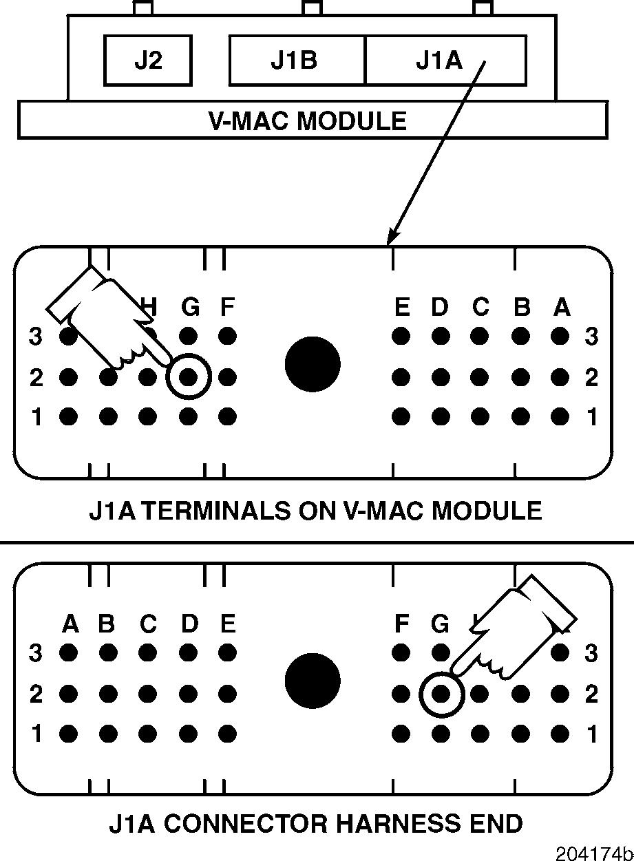
1.Visually inspect both sides of the J1A connector around pin G2 (the sensor ground [ ] line) for a repairable open.
If there is a repairable open, repair the J1A connector. Retest to be sure the problem has been corrected.
If there is not a repairable open, replace the J1A connector or V-MAC II module (if necessary). Retest to be sure the problem has been corrected.
Test 256
Checking for bad contact in the sensor connector
1.Reconnect the sensor.
2.Start the engine and flex the engine harness near the sensor.
If, at any time, the fault becomes inactive, repair or replace the sensor connector. Retest to be sure the problem has been corrected. Otherwise, replace the oil pressure sensor. Retest to be sure the problem has been corrected.
Page 41
DIAGNOSTIC CODE 1-7
DIAGNOSTIC BLINK CODE 1-7
When performing electrical tests, it is important to wiggle wires and connectors to identify intermittent connection problems.
Test 1
Checking the coolant level
1.Check the coolant level in the radiator.
If the radiator is filled to the neck of the filler tube, proceed to Test 2.
If the radiator is not filled to the neck of the filler tube, fill the radiator. Check for the cause of the low coolant and check to see if the fault is still active.
Avoid injury when checking coolant in a hot engine. Whenever possible, wait for the engine to cool prior to checking the level. Turn the radiator cap counterclockwise to the first stop, but do not depress. After the pressure has completely dissipated, press the cap downward and continue turning to remove.
Test 2
DIAGNOSTIC CODE 1-7
Checking the voltage on the sensor
Test 4
Checking the voltage on the harness
1.Turn the ignition key to the OFF position.
2.Disconnect the harness from the coolant level sensor.
3.Turn the ignition key to the ON position.
4.Measure the voltage from harness connector pin A (the signal [+] line) to a good ground.
If the voltage is greater than or equal to about 5 volts, proceed to Test 4.
If the voltage is much less than 5 volts, proceed to Test 5.
1.Turn the ignition key to the OFF position.
2.Disconnect the J1A and J1B connectors from the V-MAC II module.
3.Connect the serial link jumper into the serial communication port.
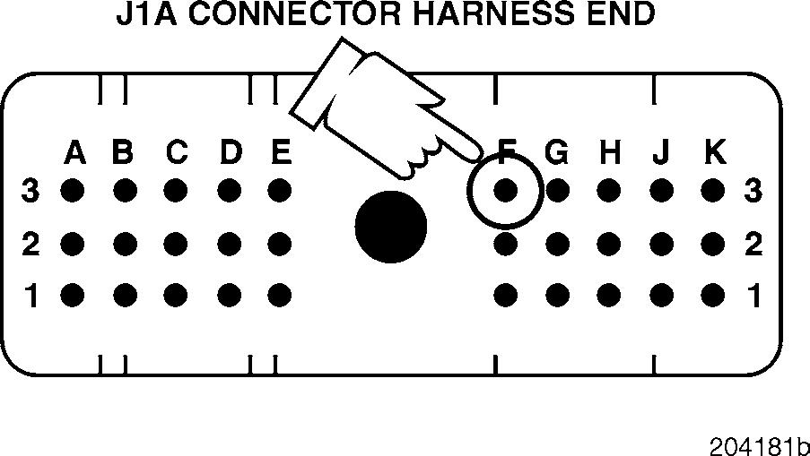
4.Measure the voltage from J1A connector pin F3 (the coolant level signal [+] line) to a good ground.
If the voltage is greater than 2 volts, locate and repair the short to voltage on the coolant level signal [+] line. Retest to be sure the problem has been corrected.
If the voltage is less than 2 volts, proceed to Test 8.
Test 5
DIAGNOSTIC CODE 1-7
Checking for continuity in the harness
Test 8
Checking for an open ground line
1.Turn the ignition key to the OFF position.
2.Disconnect the J1A connector from the V-MAC II module.
3.Connect a jumper from harness connector pin A to a good ground.
4.Check for continuity from J1A connector pin F3 (the coolant level signal [+] line) to a good ground.
If there is continuity, proceed to Test 10.
If there is no continuity, there is an open in the coolant level signal [+] line. Repair the open in the harness. Retest to be sure the problem has been corrected.
1.Disconnect the serial link jumper.
2.Connect a jumper between harness connector pins A and B.
3.Check for continuity from J1A connector pin F3 (the coolant level signal [+] line) to a good ground.
If there is continuity, proceed to Test 16.
If there is no continuity, the coolant level ground [ ] line is open. Locate and repair the open. Retest to be sure the problem has been corrected.


