8206code.fm Page 93 Tuesday, July 7, 1998 11:57 AM
DIAGNOSTIC CODE 3-5 (ELECTRICAL) Test 8 Checking for a pin-to-pin short in the harness If there is continuity with J1B connector pins P1 and P2 (ground pins), there may also be continuity with other pins. Repair the short to pins P1 and P2 first. Then retest to be sure the problem has been corrected.
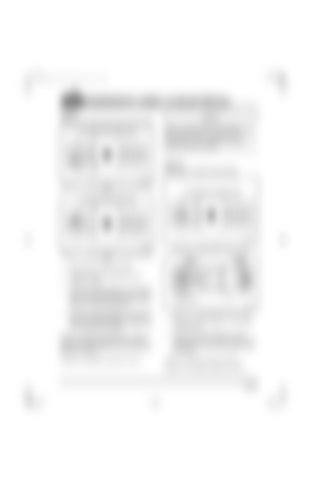
Test 16 Checking for an open in the harness Figure 146 — Continuity between Pin A1 and All Other Pins
Figure 148 — Jumper between Pins A1 and A3 Figure 147 — Continuity between Pin A3 and All Other Pins
1. Disconnect the serial link jumper. 2. Disconnect the J2 connector from the V-MAC II module. 3. Check for continuity between J1A connector pin A1 (the timing solenoid PLUS [+] line) and each of the other pins (one at a time) on the J1A, J1B and J2 connectors. Figure 149 — Continuity between Pins A and B
4. Check for continuity between J1A connector pin A3 (the solenoid MINUS [−] line) and each of the other pins (one at a time) on the J1A, J1B and J2 connectors.
1. Connect a jumper between J1A connector pins A3 and A1.
If there is continuity with another pin, repair the short in the harness between the pins which showed continuity. Retest to be sure the problem has been corrected.
2. Check for continuity between harness connector pins A (the signal [+] line) and B (the ground [−] line), on the solenoid end of the harness.
If there is no continuity, proceed to Test 16.
If there is continuity, proceed to Test 32. If there is no continuity, proceed to Test 33.
Page 93


