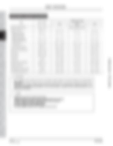
TIGHTENING TORQUES FOR ENGINE Size x Pitch
Tightening torque N•m
kgf-m
ft-lb
Cylinder head screws
M11 x 1.25
Refer to “NOTE” below
Head cover bolt
M8 x 1.0
8.8 ~ 11.8
0.9 ~ 1.2
6.5 ~ 8.7
* Bearing case bolt 1 (Case cover bolt)
M9 x 1.25
46.1 ~ 51.0
4.7 ~ 5.2
34.0 ~ 37.6
* Bearing case bolt 2 (Case mounting bolt)
M10 x 1.25
68.6 ~ 73.6
7.0 ~ 7.5
50.6 ~ 54.2
* Flywheel bolt
M12 x 1.25
98.1 ~ 107.9
10.0 ~ 11.0
72.3 ~ 79.6
* Connecting rod bolt
M8 x 1.0
46.1 ~ 51.0
4.5 ~ 5.0
34.0 ~ 37.6
Rocker arm bracket bolt
M10 x 1.25
60.8 ~ 70.6
6.2 ~ 7.2
44.8 ~ 52.1
Drain plug
M12 x 1.25
32.4 ~ 37.3
3.3 ~ 3.8
23.9 ~ 37.3
Glow plug
M10 x 1.25
19.6 ~ 24.5
2.0 ~ 2.5
14.5 ~ 18.1
Oil switch
PT1/8
14.7 ~ 19.6
1.5 ~ 2.0
10.8 ~ 14.5
Nozzle holder assembly
M20 x 1.5
49.1 ~ 68.7
5.0 ~ 7.0
36.2 ~ 50.6
Injection pipe nut
M12 x 1.5
24.5 ~ 34.3
2.5 ~ 3.5
18.1 ~ 25.3
Temperature meter switch
PT1/8
13.7 ~ 15.7
1.4 ~ 1.6
10.1 ~ 11.6
D.C alternator pulley nut
M15 x 1.5
39.2 ~ 53.9
4.0 ~ 5.5
28.9 ~ 39.8
CAUTION • •
For * marked screw, bolts and nuts on the table, apply engine oil to their threads and seats before tightening. The letter “M” in Size × Pitch means that the screw, bolt or nut dimension stands for metric. The size is the nominal outside diameter in mm of the threads. The pitch is the nominal distance in mm between two threads.
NOTE •
•
Tightening torque for cylinder head bolts Tightening order (using the angle controlled tightening method) 1st step: Tighten the bolts to 4.0 kgf-m (39.2 N•m, 28.8 ft-lb) 2nd step: Rotate the bolts additional 90° 3rd step: Rotate the bolts additional 80° For more details, refer to 7.6.1 “Cylinder head removal.”
HYDRAULIC ELECTRIC & DIAGNOSIS SYSTEM A/C AND INDEX HEATER
3-10 50 of 450
DR72-W00
Dealer Copy -- Not for Resale
Item
HYDRAULIC STEERING SYSTEM
STEERING SYSTEM FRONT AXLE
FRONT BRAKE AXLE
REAR BRAKE AXLE
REAR HSTAXLE
TRANSMI SSION HST
TRANSMI SSION TRANSMISSION
CLUTCH
ENGINE
GENERAL
SAFETY FIRST
ENGINE - SPECIFICATIONS


