
1 minute read
HYDRAULIC SYSTEM - DISASSEMBLY, SERVICE AND ASSEMBLY


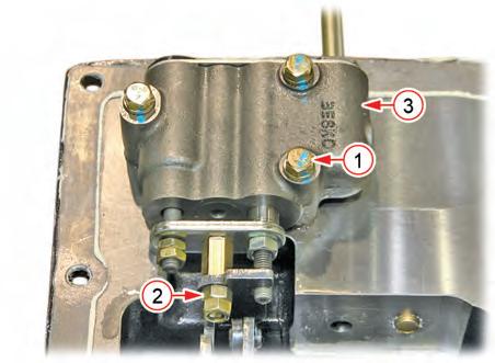
8. Pull out the mounting spring pin (2) for the hydraulic arm (1) to disconnect the hydraulic arm and hydraulic rod (3).
10. Unscrew the lever support mounting bolt (1) and turn the lever support assembly to loosen the mounting screw (2). Then, disconnect the position control lever arm (3) and remove the lever support assembly (4).


Remark
• Apply Loctite® 5060 or equivalent sealant to the mounting screw when the reinstalling it.
• Apply liquid gasket to the mating surfaces of between of the lever supprot and hydraulic cylinder.
9. Remove the snap ring (1), position control link (2) and mounting shaft (3).
6.3.2.
HYDRAULIC SYSTEM - DISASSEMBLY, SERVICE AND ASSEMBLY

HYDRAULIC CYLINDER ASSEMBLY REASSEMBLY
Remark
BUSHING AND OIL SEAL END-PLAY
1. Assemble in the reverse order of disassembly.
(1) BUSHING (2) BUSHING (3) OIL SEAL
• End-play after bushing installation
A,B: 0,5 ~ 1.5 mm (0.0197 - 0.0591 in)
2. When installing the hydraulic arm shaft (1) and hydraulic arm (2), align the mounting bolt holes and install them in the correct direction as shown in the figure. When tightening the mounting bolt, apply LOCTITE® 272 or equivalent to it in advance. Also, when installing the bushing or oil seal to the hydraulic arm shaft mounting section, make sure to use a tool and apply grease to it.
3. Install the O-ring (1) and backup ring (2) for the hydraulic piston as shown in the figure. (Be careful with the installation direction.)

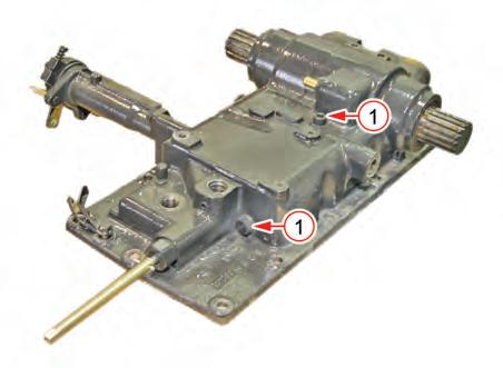
4. When installing the cylinder to the case, apply Loctite® 577 or equivalent to the hex. slotted bolt (1) in advance.

HYDRAULIC SYSTEM - DISASSEMBLY, SERVICE AND ASSEMBLY

6.4 LIFT CONTROL VALVE


Mounting


