
2 minute read
FRONT AXLE - MEASUREMENT AND ADJUSTMENT


4.5 BACKLASH FOR DIFFERENTIAL PINION AND DIFFERENTIAL SIDE GEAR
4.6 BACKLASH FOR SPIRAL BEVEL PINION AND 23 SPIRAL BEVEL GEAR
T46W813A
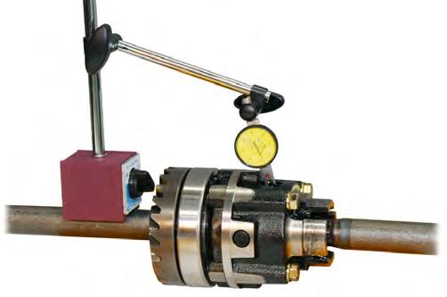
1. Set the front differential case assembly with both differential gear shafts inserted as shown in the figure.
2. Install the dial indicator (lever type) so that its pointer contacts with the surface of the differential side gear through the hole of the differential case.
3. Hold one differential gear shaft with a hand and measure the backlash by rotating the other differential gear shaft.
Standard backlash: ...... 0.1 ~ 0.3 mm
(0.004 ~ 0.012 in)
1. Assemble the spiral bevel pinion shaft, 21 bevel gear, differential case and axle support differential gear shaft as shown in the figure.
2. Set the lever type dial indicator so that it contacts with the spline of the spiral bevel pinion shaft as shown in the figure.
3. With both differential gear shaft fixed, measure the backlash by moving the spiral bevel pinion shaft by hand lightly.
• Backlash
Standard spline: 0.07 ~ 0.21 mm (0.003 ~ 0.008 in)
Standard gear teeth radius: 0.1 ~ 0.3 mm (0.004 ~ 0.012 in)
• Calculation of standard backlash for spline
4. Adjust the shim (2) if the 21 bevel gear (1) should be moved to adjust the backlash.
= Standard backlash for gear teeth x spline radius
Center line radius of teeth contact
= 0.1 ~ 0.3 mm x 12 mm 17 mm = 0.07 ~ 0.21 mm (0.003 ~ 0.008 in)
T46W814A
4. If necessary, replace the shim (1) installed on the back of the differential side gear to adjust the backlash. However, the shims with the same thickness should be installed in both side gears.
Size of adjusting shim: ..... 0.8, 1.0, 1.2 mm
(Standard shim: 1.0 mm)
• Size of shim: 0.8, 1.0, 1.2 mm (standard shim: 10 mm)
5. Change the collar 1 (4) and collar 2 (5) which is installed on front and rear sides of the shaft if the spiral bevel pinion shaft (3) should be moved. However, the overall thickness of front and rear collars should be 9 mm.
• Size of adjusting collar
Collar 1: 2.8, 2.9, 3.0, 3.1, 3.2 mm (standard collar: 3.0 mm)
Collar 2: 5.8, 5.9, 6.0, 6.1, 6.2 mm (standard collar: 6.0 mm)
6. Measure the contact area if the shim or collar has been adjusted.
• This procedure can be skipped if adjusting shim is unnecessary.
4.7 TOOTH CONTACT OF SPIRAL BEVEL GEAR
1. Clean the teeth after removing the spiral pinion shaft (3) and the ring gear (1).
2. Coat all the teeth of the pinion shaft (3) with contact grease and reassemble it.
3. Turn the pinion shaft for approx. 10 turns and check the dimension of contact area by measuring the dimension with contact grease on the teeth of the ring gear (1).
• The contact area should be over 35% of the entire teeth area and the center of the contact mark should be close to the center of the pinion in height. Also, the center of the contact mark should be located on the between the 1/3 ~ 2/3 spot from the toe of the teeth to the center of the teeth in length.


