3 minute read
ENGINE - MEASUREMENT AND ADJUSTMENT 5. MEASUREMENT AND ADJUSTMENT


5.1 FAN BELT
Measure the deflection by depressing the center of the belt between the fan drive pulley and the alternator pulley at 49 N (5 kgf, 11 lb) of force. If the deflection is out of the specified value, loosen the bolts and nuts and adjust the location of the alternator. If the belt is damaged or worn (see figure), replace the belt.
....... 5 ~ 10 mm (0.20 ~ 0.39 in)
5.2 PISTON COMPRESSION PRESSURE MEASUREMENT
1. Run the engine until it is warmed up.
2. Stop the engine and remove the air cleaner, the muffler and all nozzle holders.
3. Connect a compression tester to the nozzle holder hole.
4. Pull the stop lever or close the fuel filter with the cock to cut the fuel and crank the engine with the starter motor for 5 to 10 seconds.
5. Measure the maximum pressure several times while engine running.
6. If the pressure does not reach the allowable limit, apply few drops of oil to the cylinder wall through the nozzle holder hole and check the pressure again.
7. If the pressure rises after applying the oil, check the cylinder wall and piston ring for wear.
8. If the pressure is still low, check the top clearance, valve clearance and cylinder head. Compression
Caution
• Check the compression pressure and adjust the valve clearance to the ����� value.
ENGINE - MEASUREMENT AND ADJUSTMENT
5.3 VALVE CLEARANCE
1. The valve clearance should be measured only when the engine temperature is same to the ambient temperature.
2. Disconnect the negative battery cable.
3. Remove the cylinder head cover.
4. Turn the crankshaft using the crankshaft turning socket until the intake valve of the No. 2 cylinder and the exhaust valve of the No. 3 cylinder move simultaneously and the rocker arm height of these two valves is same.
5.4 VALVE LIFT (DEFLECTION AND WORN CONDITION OF VALVE CAM, TAPPET, PUSH ROD, ROCKER ARM, ETC.)
1. Remove the cylinder head cover.
2. Adjust the valve clearance according to the section 5.3.
3. Set the dial gauge so that its pointer is on the valve. The valve should be closed and the rocker arm should move as much as the freeplay.
4. Measure the max. valve movement while turning the crankshaft.
5. Measure the max. vertical movement of other valves according to the above process.
6. The vertical movement for all valves should be in the tolerance range of 0.5 mm (0.02 in). If the measured value is out of the tolerance, check the corresponding valve for the deflection of the pushrod, worn condition, engagement with the tappet, worn tappet and worn valve cam.
1. Measure the clearance of the intake and exhaust valves of the No. 1 cylinder, the exhaust valve of the No. 2 cylinder and the intake valve of the No. 3 cylinder. Adjust the clearance if necessary.
2. Turn the crankshaft 360° and measure the clearance of the intake valve of the No. 2 cylinder and the exhaust valve of the No. 3 cylinder. Adjust the clearance if necessary.
ENGINE - MEASUREMENT AND ADJUSTMENT
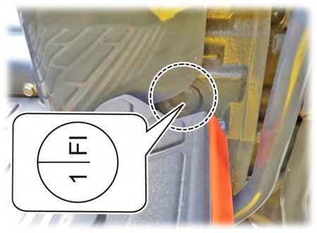
5.5 INJECTION TIMING MEASUREMENT AND ADJUSTMENT
Notes
Perform the work with the engine installed in the tractor.
1. Remove the engine stop solenoid.
- When turning the crankshaft, use a special service tool (socket) for turning the crankshaft by engaging it with the socket wrench.
2. Remove the timing check window cover on the right side of the flywheel housing.
3. Turn the flywheel to find 1 FI mark on the flywheel.
4. When the mark was found, turn the crankshaft counterclockwise approx. 30° (when looking at the front of the engine).
- "1 FI" means the injection timing of the No. 1 cylinder.
1. Remove the No. 1 high pressure pipe.
2. Unscrew the nozzle holder (1) slightly and tighten it when it is filled with fuel.
1. Remove the fuel in the nozzle holder with clean cloth and leave only small amount of fuel.
2. Observe the fuel of the nozzle holder while turning the crankshaft clockwise (when looking at the front of the engine) slowly.
3. When the amount of the fuel in the nozzle holder increases abruptly, that moment is the injection timing.
- If the fuel increases too much, it means that the injection timing is passed already. Repeat the above process to identify the moment when the amount of fuel starts to increase.
- If the fuel does not increase, it means that it is the exhaust cycle. Therefore, turn the crankshaft 360° to find the compression cycle and repeat the above procedures.
4. Mark the measured injection timing on the flywheel through the timing window and measure the distance between the "1 FI" and the mark you made.
5. To advance the injection timing, reduce the amount of shims. To delay the injection timing, increase the amount of shims.
5.6 OIL PRESSURE MEASUREMENT
- BTDC: Before top dead center
Example)
If the measured injection timing is on the 2.74 mm above the FI mark, it means that the injection timing is 1° advanced. Therefore, the measured injection timing is BTDC 19°. In this case, the injection is adjusted to 18° if adding 0.1 mm of shim under the fuel injection pump.
1. Remove the oil pressure switch and install the adapter and the pressure tester.
2. Start and warm up the engine. Then, measure the oil pressure at idle and rated speed.
3. If the oil pressure is less than the allowable limit, check the oil level, oil filter, oil pump relief valve, oil passages and oil clearance.


