6 minute read
TRANSMISSION - DISASSEMBLY, SERVICE AND ASSEMBLY


5. Undo the shift rod stopper (1) and remove the plug (2), snap ring (3), PTO shift fork (4), PTO shift rod (5), steel ball (6), spring (7).
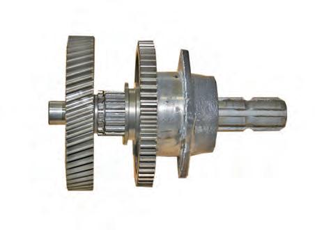
7. Remove the PTO shaft (1) in the transmission case by tapping outside direction to remove the ball bearing (2), thrust spacer (3), 58 gear needle bearing (4), shifter (PTO 1 stage model), 58 plain gear (PTO 2 stages model) (5) from the transmission case.
Remark
• When installing the thrust spacer, its groove should face the gear side.
• Apply ThreeBond® 1372 or equivalent adhesive when the sleeve install to the PTO shaft inside.
• Make sure to apply grease on the mating surface of oil seal.
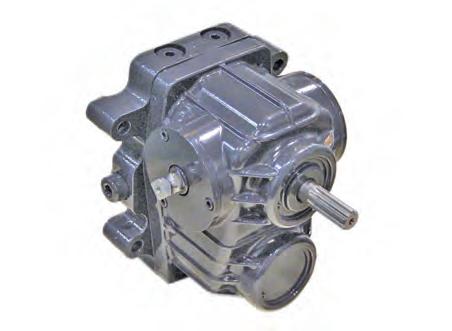
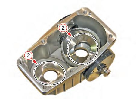
6. Unscrew the mounting bolts (1) of PTO bearing case and remove the PTO bearing case (2).


Remark
• Apply liquid gasket (Dow Corning® 780 or equivalent) to the mating surfaces of PTO bearing case.
HST - SPECIFICATIONS
1. SPECIFICATIONS
1.1 GENERAL SPECIFICATIONS 1.2
1. Hydraulic oil Bobcat Transmission /
1.3 MAJOR TIGHTENING TORQUE
Forward/reverse relief
14. Pressure test port
1. HST type ........................... Variable piston pump
15. Front cover (head) bolt (M10)
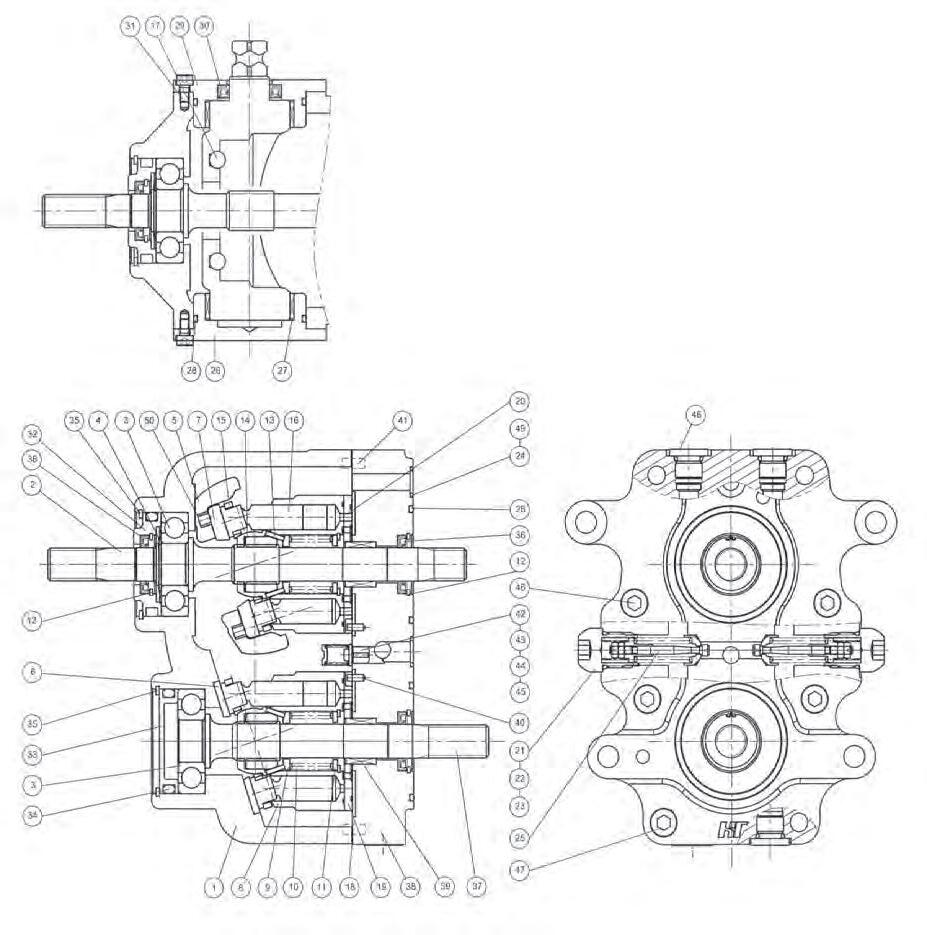
1.4 HST STRUCTURE & COMPONENTS
1.4.1.
1.4.2. COMPONENTS
HST - SPECIFICATIONS
(1) MAIN CASING
(2) SHAFT (P)
(3) BALL BEARING
(4) SNAP RING
(5) SWASH PLATE (P)
(6) SHOE PLATE
(7) CYLINDER BLOCK

(8) SPRING SEAT 1
(9) SPRING
(10) SPRING SEAT 2
(11) SNAP RING
(12) PIN
(13) BALL GUIDE
(14) RETAINER
(15) PISTON ASSY
(16) GASKET
(17) VALVE PLATE (M)
(18) VALVE PLATE (P)
(19) PLUG_REL
(20) O-RING
(21) SPRING_REL
(22) O-RING
(23) RELIEF V/V ASSY
(24) COVER(B)
(25) DX BEARING
(26) O-RING
(27) COVER (A)
(28) OIL SEAL
(29) WRENCH BOLT
(30) COVER (P)
(31) COVER (M)
(32) O-RING
(33) SNAP RING
(34) OIL SEAL
(35) SHAFT (M)
(36) V/V BLOCK
R69W602A
(37) NEEDLE BEARING
(38) PIN
(39) PIN
(40) CHECK
(41) SPRING_CHECK
(42) SPRING HOLDER
(43) WRENCH BOLT
(44) PLUG ASSY
(45) WRENCH BOLT
(46) WRENCH BOLT
(47) RUBBER CAP
(1) MAIN CASING
(2) SHAFT (P)
(3) BALL BEARING
(4) SNAP RING
(5) SWASH PLATE (P)
(6) SHOE PLATE
(7) CYLINDER BLOCK
(8) SPRING SEAT 1
(9) SPRING
(10) SPRING SEAT 2
(11) SNAP RING
(12) PIN
HST - SPECIFICATIONS
(13) BALL GUIDE
(14) RETAINER
(15) PISTON ASSY
(16) GASKET
(17) VALVE PLATE (M)
(18) VALVE PLATE (P)
(19) PLUG_REL
(20) O-RING
(21) SPRING_REL
(22) O-RING
(23) RELIEF V/V ASSY
(24) COVER (B)
(25) DX BEARING
(26) O-RING
(27) COVER (A)
(28) OIL SEAL
(29) WRENCH BOLT
(30) COVER (P)
(31) COVER (M)
(32) O-RING
(33) SNAP RING
(34) OIL SEAL
(35) SHAFT (M)
(36) V/V BLOCK
R69W603B
(37) NEEDLE BEARING
(38) PIN
(39) PIN
(40) CHECK
(41) SPRING CHECK
(42) SPRING HOLDER
(43) WRENCH BOLT
(44) PLUG ASSY
(45) WRENCH BOLT
(46) WRENCH BOLT
(47) RUBBER CAP
2. OPERATING PRINCIPLE
2.1 STRUCTURE AND FUNCTION OF HST ►
HST - OPERATING PRINCIPLE
2.1.1. BASIC PRINCIPLE OF HST
Hydraulic Pump

The HST (Hydrostatic Transmission) is mainly composed of the hydraulic pump and the hydraulic motor. The hydraulic pump rotates with the output shaft of the engine to supply the operating fluid. At this point, the kinetic energy is converted to the hydraulic energy. The fluid supplied by the pump is converted back to the kinetic energy by the hydraulic motor. This energy runs the range shift shaft that is connected to the shaft of the hydraulic motor to transfer the power to the wheels. The driver can change the rotating direction and the rotating speed of the HST output shaft by controlling the amount of fluid in the HST pump.
The input shaft (1) of the HST pump is directly connected to the flywheel in the engine. Each piston is engaged to the swash plate (4) and rotates as it slides on the swash plate. When the swash plate (4) is tilted, the piston rotates and reciprocates simultaneously to generate the hydraulic pressure. When the shaft rotates one turn, each piston reciprocates one time. Therefore, the compression process is derived in the half of the cylinder, which is called the high pressure section, and the suction process is derived in other half of the cylinder, which is called the low pressure section. If the swash plate is tilted to the opposite direction, the high and low pressure sections are switched and the direction of the fluid flow changes. The tilt angle of the swash plate is adjusted between -18° and +18° and it determines the forward and reverse driving direction and speed.
HST - OPERATING PRINCIPLE
2.1.2. FUNCTION HST CHARGE PUMP
The operating fluid compressed in the pump is sent to the hydraulic motor to run the motor.

The hydraulic motor consists of the cylinder block and nine pistons (1). However, the swash plate that engages each piston is fixed to 18°. When the operating fluid from the high pressure section in the pump flows into the piston, the piston is extended and tries to push out the swash plate. However, the pistons slide on the inclined swash plate since it is fixed. Due to this sliding force, the cylinder block rotates.
The pistons are extended during half of turning and are retracted during the other half of turning. When they are retracted, the operating fluid is supplied to the inlet of the pump (low pressure section) to complete one cycle. The rotating speed of the hydraulic motor is proportional to the amount of fluid supplied from the hydraulic pump. In other words, the rotating speed of the motor changes proportionally to the tilt angle of the swash plate in the pump that makes continuously variable shift possible. Also, as the tilt angle of the swash plate in the pump changes, the flow direction of the fluid supplied to the motor changes and then the rotating direction of the hydraulic motor changes so that the forward and reverse driving direction is switched.
The leakage is unavoidable from the sliding surface of piston. Since piston end slides on the swash plate (2), there is oil hole (1) at the end of the piston to leak the operating oil in the HST circuit for lubrication of the swash plate and piston.
The oil is continuously leaked in the HST circuit during the operating process and the amount of oil should be replenished.
Basically, the HST is equipped with its own separate charge pump but for this model, the oil from the steering unit is used.
The steering gear pump (driven by fuel cam shaft in the engine), which supplies oil to the steering system, takes over the function of the charge pump in HST.
The route of the charge fluid is as follows:
Transmission case → oil filter → suction pipe → steering gear pump → steering unit → HST filter → HST → oil cooler → transmission case
2.1.3. CHARGE RELIEF VALVE
Oil leakage in the HST circuit is not constant and changes depending on the rotating speed or the load. A sufficient amount of oil should be supplied to prepare for the worst condition. Therefore, oil is left over in normal conditions and the charge relief valve drains this excessive oil.
The charge relief valve is set to be open when the hydraulic pressure goes over 4 ~ 6 kgf/cm2 (57 ~ 85 psi). When driving the tractor forward or backward, the high pressure is formed in the circuit of the compression section and the low pressure is formed in the circuit of the suction section in the pump of the system. And, as the driving direction is changed (forward / reverse), the high pressure section and the low pressure section are switched over.

2.1.4. HIGH PRESSURE RELIEF VALVE

As other hydraulic systems, the HST is equipped with the relief valve for protection in case of overload. If excessive tractional load is applied to the tractor, the motor in the HST slows down or stops due to the external load and the HST pump connected to the engine rotates as long as the engine rotates to supply hydraulic pressure to the motor. If there is no relief valve in this case, the internal pressure and temperature of HST greatly increase and the internal components are seriously damaged. The relief valve pressure prevents the internal pressure of HST from rising over 300 kgf/cm2 (4,266 psi). When the relief valve opens, the operating fluid in the high pressure section is sent to the low pressure section or is drained to the transmission case through the charge relief valve.
The relief valve is installed to the high pressure section and the low pressure section. It takes over the function of the check valve.
(* The high pressure section and the low pressure section are switched over when switching from forward driving to reverse driving and vice versa.)
2.2 OPERATION OF HST
HST - OPERATING PRINCIPLE HYDRAULIC SYSTEM ELECTRIC & DIAGNOSIS
The pressure in the circuit is same with the charge relief pressure when it is in NEUTRAL.
(1) CONTROL LEVER
(2) HST PUMP
(3) HST MOTOR
(4) VALVE PLATE
TRANSMI SSION HST 6-11 DR72-W00
2.2.2. FORWARD DRIVING
When the HST pedal for forward is depressed, the swash plate in the HST pump tilts. Therefore, the piston reciprocates as the pump shaft rotates. Then, the hydraulic pressure produced by this process runs the hydraulic motor.
2.2.3. REVERSE DRIVING
When the HST pedal for reverse is depressed, the swash plate in the HST pump is tilted to opposite angle of forward. Therefore, the piston reciprocates as the pump shaft rotates. Then, the hydraulic pressure produced by this process runs the hydraulic motor. When the swash plate in the HST pump is tilted to the opposite direction, the fluid flow direction the rotating direction of the hydraulic motor are reversed.
T46W528A
(1)
(2)
(3)
(4)


