2 minute read
HYDRAULIC SYSTEM - DISASSEMBLY, SERVICE AND ASSEMBLY


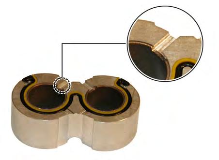
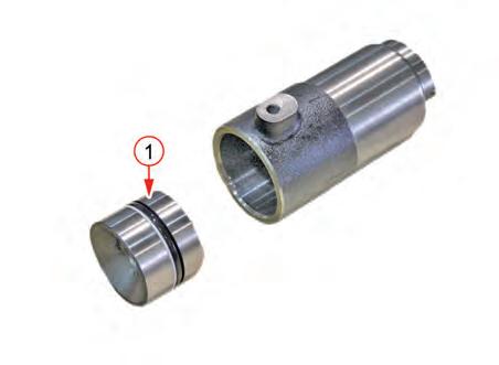
5. Check the back-up ring in the thrust block and the seal ring for damage.
6. Check the bushing of the thrust block for wear. Also, check if the position of bushing has been changed.
• If the groove on the bushing of the section A is not aligned with the groove of the thrust block, the position of bushing has been changed. In this case, replace the bushing.
7. Check the dowel pin prior to assembly of the front cover, body, middle flange and rear cover.
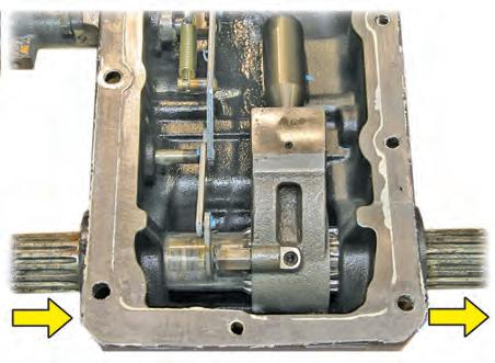
9. Be careful with the direction of the drive shaft and driven shaft of the gear shaft.
10. Tighten the cover tightening bolt to the specified torque.
• Bolt tightening torque 44.1 N•m 4.5 kgf-m 32.5 ft-lb
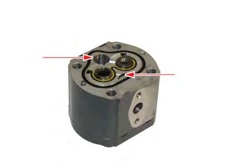
8. When assembling the thrust block, the seal should face the drain section and the section without the seal should contact with the gear.
HYDRAULIC SYSTEM - DISASSEMBLY, SERVICE AND ASSEMBLY
6.2 AUX. HYDRAULIC VALVE (DOUBLE ACTING VALVE)
1. Park the tractor on level ground, stop the engine and apply the parking brake.
2. Remove the fender.
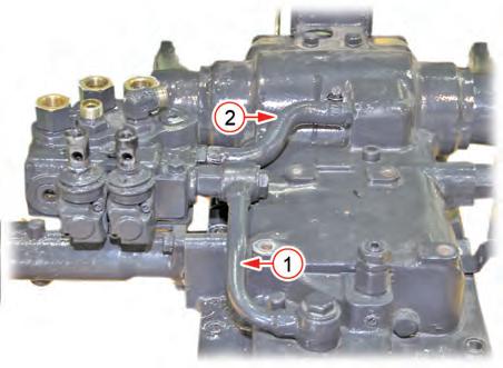
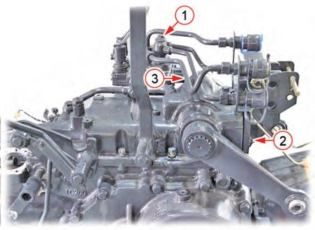
5. When necessary, unscrew the socket support bolt (1) to disconnect the whole external hydraulic pipe. Otherwise, undo the quick coupler (2) to disconnect the corresponding pipe only.


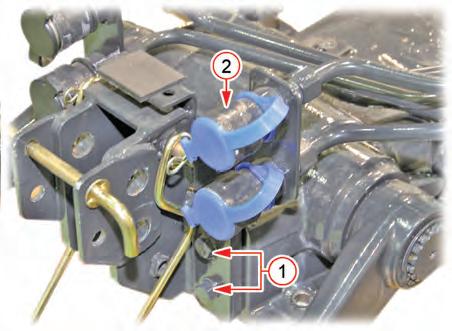
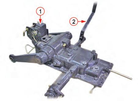
3. Unscrew the lever boss mounting bolts (1) and disconnect the double acting lever (2).
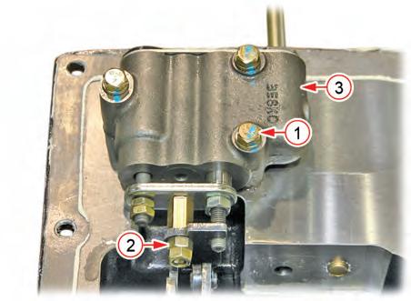
4. Loosen the joint bolts (1) and nuts (2). Then, disconnect the external hydraulic pipes (3) one by one.
6. Disconnect the hydraulic tube-CA (1) and hydraulic tube-T (2).
HYDRAULIC SYSTEM - DISASSEMBLY, SERVICE AND ASSEMBLY
6.3 HYDRAULIC CYLINDER
1. Remove the fender and seat base assembly by lifting them as a set.
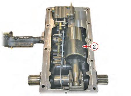
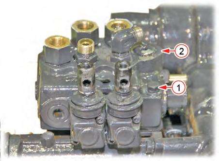
7. Unscrew the double acting valve mounting bolts (1) and remove the double acting valve assembly (2).
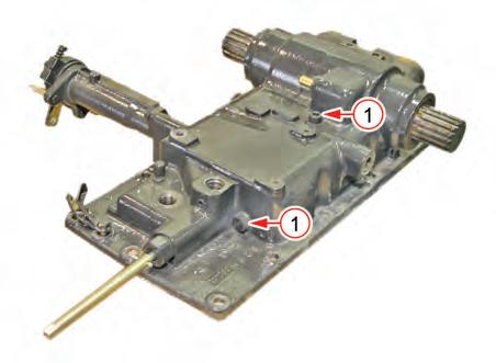
2. Unscrew the double acting valve joint bolt (1) and socket support bolt (2) to remove the whole external hydraulic pipes (3).
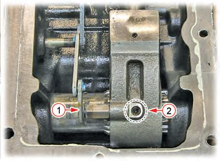
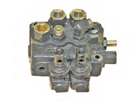
3. Unscrew the double acting valve mounting bolt (1) to remove the double acting valve (2).
HYDRAULIC SYSTEM - DISASSEMBLY, SERVICE AND ASSEMBLY


6.3.1. HYDRAULIC CYLINDER ASSEMBLY DISASSEMBLY
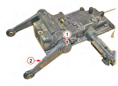
1. Remove the top link bracket (1) and PTO shift lever (2).
2. Remove the snap rings (1) from the both ends of the lift arm. Then, remove the both lift arms (2).
4. Unscrew the mounting bolts (1) for the hydraulic cylinder and transmission case and secure the hydraulic cylinder assembly with a hoist. Then, lift the assembly slowly to remove it.

Remark
• Apply liquid gasket (Dow Corning© 780 or equivalent) to the mating surfaces of transmission case before assembly when the reinstalling hydraulic cylinder.
3. Remove the relief valve (1).
HYDRAULIC SYSTEM - DISASSEMBLY, SERVICE AND ASSEMBLY
4. Loosen the hex. slotted bolts (1) from the top and front surfaces of the cylinder case sufficiently. Then, turn the cylinder case upside down and loosen the bolts completely to remove the cylinder (2) from the case.
5. Remove the piston (1) from the cylinder.
7. After disconnecting the link (1), unscrew the hydraulic arm mounting bolt (2) with a hex. wrench. Then, tap the hydraulic arm shaft in the arrow direction shown in the figure to remove it.