4 minute read
FRONT AXLE - MEASUREMENT AND ADJUSTMENT 4.8 TOOTH CONTACT FOR UPPER BEVEL GEARS AND FINAL DRIVE BEVEL GEARS


Remark
• The engaging efficiency of the teeth is judged by the contact area since the backlash of the upper and lower bevel gears cannot be measured. In general, the backlash is within the standard range if the contact area is within the specified value since the contact condition is considered when determining the initial standard backlash.
1. Lift the front axle using a hydraulic jack or a hoist, remove the front tires and drain oil from the axle completely.
2. Remove the 16 bevel gear (1) and 11 bevel gear (2) refering to the section "Servicing" in this chapter. Then, remove any oil on the teeth.
3. Coat all the teeth of the 11 gear with contact grease and reassemble it.
4. Remove the axle cover (3) and clean the teeth of the 42 bevel gear (4) and 9 bevel gear (5).
5. 5. Coat all the teeth of the 9 bevel gear (5) with contact grease.
6. 6. Reassemble the axle cover (3) and rotate the axle using a hand to check any defect.
7. Check that the front axle is firmly supported. Then, start the engine to rotate the front axle for approx. 10 turns.
8. Stop the engine and disassembly the bevel gears to check the teeth engagement.
9. If the contact area is abnormal, adjust the shims (6, 7 and 8 in the figure) and measure the contact area again.
• Size of shims
Upper bevel shim (6): 0.8, 1.0, 1.2 (standard shim: 1.0 mm)
Lower bevel shim (7): 1.4, 1.6, 1.8 (standard shim: 1.6 mm)
Refer to section 4.7 for measuring method.
Remark
• Bevel gear backlash: 0.15 ~ 0.35 mm
• Tooth contact check: At three equally divided positions in the circle circumference, the contact area should be over 35% of the teeth area and the center of the contact mark should be one third to half of the entire length.
FRONT AXLE - EXPLODED VIEW
5.
Notes
• The manufacturing parts are subject to change without notice. Therefore, check the parts catalog or electronic manual for latest information.
Components
(8)
(9)
(10)
COMPONENTS
(2)
(4)
(5)
(6)
(7)
FRONT AXLE - EXPLODED VIEW
(8)
(9)
(10)
(11)
(12)
(13)
(14)
R69W902A
(15)
(16)
(17)
(18)
(19)
COMPONENTS
Components
FRONT AXLE - EXPLODED VIEW
COMPONENTS
(1) SPIRAL BEVEL GEAR ASSEMBLY
(2)
(3)
(4)
(5)
(6)
FRONT AXLE - EXPLODED VIEW
(7) COLLAR 1, AXLE ADJUSTING FR
(8) COLLAR 1, AXLE ADJUSTING FR
(9) BEARING, TAPER ROLLER
(10) SPACER
(11) COLLAR 2, AXLE ADJUSTING FR
(12)
(13) COLLAR 2, AXLE ADJUSTING FR
(14) COLLAR 2, AXLE ADJUSTING FR
(15) COLLAR 2, AXLE ADJUSTING FR
(16) SNAP RING
(17) NUT, 28
(18) SEAL, OIL
FRONT AXLE - DISASSEMBLY, SERVICE AND ASSEMBLY
6. DISASSEMBLY, SERVICE AND ASSEMBLY
6.1 FRONT AXLE OIL SEAL REPLACEMENT
1. Park the tractor on level ground, stop the engine and apply the parking brake.
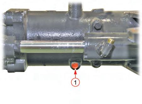
Unscrew the drain plug (1) of the front axle to drain front axle oil.
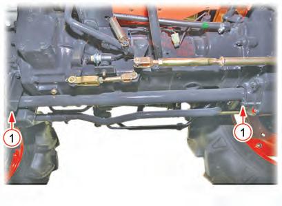
3. Place a stand or hydraulic jack under the front axle and unscrew the front wheel mounting bolts (1) to remove the front wheels.
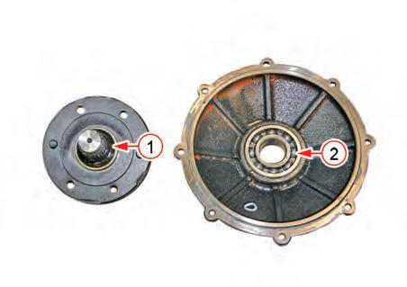
4. Unscrew the front axle cover mounting bolts (1) to remove the front axle cover assembly (2).


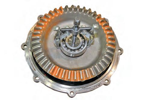
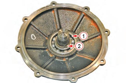
5. Pull out the ball bearing (1) and 42 bevel gear (2) from the front axle cover assembly in order using a bearing puller.
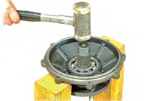
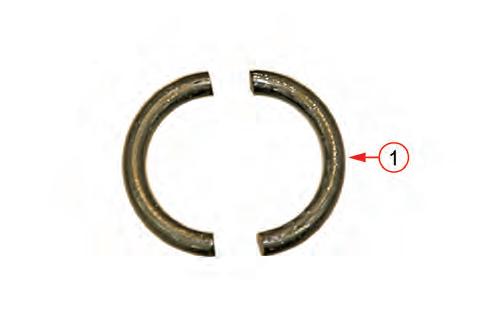
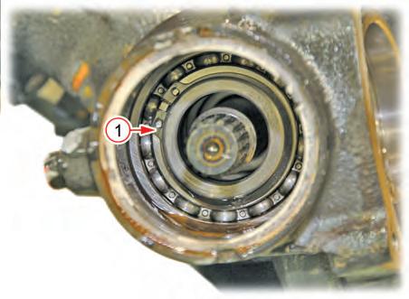
6. Pull out the stop ring (1) from the front axle cover assembly. Then, tap the front axle with a rubber hammer as shown in the figure to separate it from the cover.
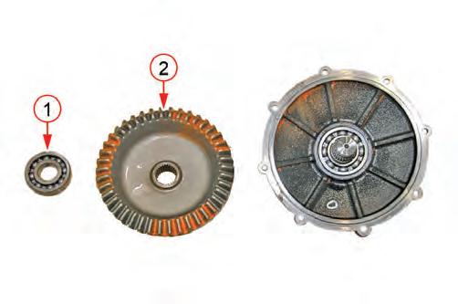
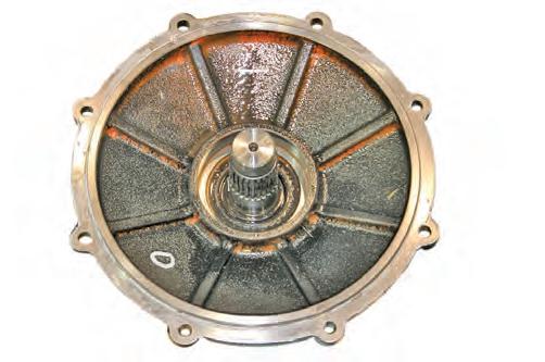
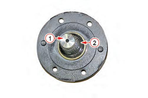
7. Remove the oil seal (1) and the ball bearing (2) from the front axle and front axle cover.
FRONT AXLE - DISASSEMBLY, SERVICE AND ASSEMBLY
Front Axle Cover Assembly
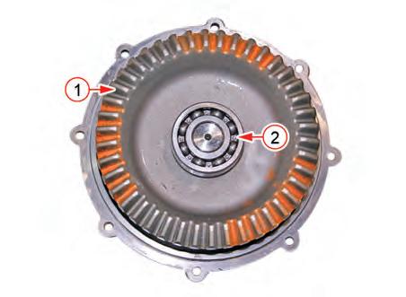
4. After inserting the 42 bevel gear (1) to front axle, the stop ring should be into the groove of 42 bevel gear using a jig. Then, install the ball bearing (2).
5. Install the front axle cover assembly (1) to the front axle case (2).
Important
• Tighten the mounting bolts (M8) diagonally in several steps.
Mounting bolt (M8) tightening torque………23.5 ~ 27.5 N•m
2.4 ~ 2.8 kgf-m 15.9 ~ 20.3 ft-lb
Remark
• Apply liquid gasket (Dow Corning© #780 or equivalent) to the mating surfaces of front axle case when the reinstalling front axle cover.
FRONT AXLE - DISASSEMBLY, SERVICE AND ASSEMBLY


6.2 BEVEL GEARCASE AND FRONT AXLE CASE DISASSEMBLY AND ASSEMBLY
1. Park the tractor on level ground, stop the engine and apply the parking brake
2. Place a stand under the front axle, remove the front wheels and drain front axle oil.
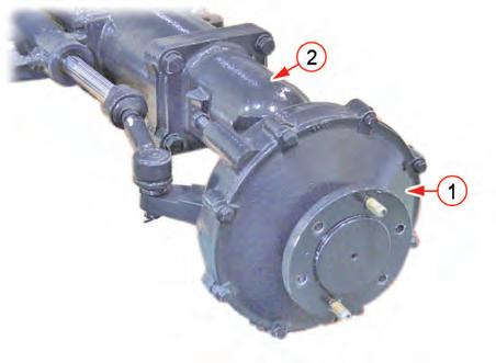
3. Remove the tie-rod end (1) and unscrew the front axle cover mounting bolts (2). Then remove the front axle cover assembly (3).
4. Unscrew the bevel gearcase mounting bolts (1) and remove the bevel gearcase and front axle case assembly (2).
Mounting bolt, nut (M14) tightening torque………166.6 ~ 196.0 N•m
17.0 ~ 20.0 kgf-m
122.4 ~ 144.0 ft-lb
REMARK
• Apply liquid gasket (Dow Corning© #780 or equivalent) to the mating surfaces of bevel gearcase when the reinstalling front axle support.
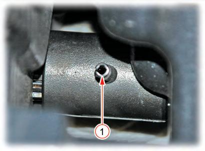
5. Pull out the plug (1) from the under the front axle case and remove the snap ring (2). Then adjust shim (3), 9 bevel gear, ball bearing assembly (4) and bevel gear shaft (5).


Remark
• Apply liquid gasket (Dow Corning© #780 or equivalent) to the mating surfaces of front axle case when the reinstalling plug.
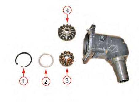
6. Pull out the snap ring (1) from the bevel gearcase and remove the bevel gearcase (2) from the front axle case (3).
7. Pull out the snap ring (1) of 11 bevel gear and remove
FRONT AXLE - DISASSEMBLY, SERVICE AND ASSEMBLY

the adjust shim (2), 11 bevel gear (3), 16 bevel gear (4) in order.
8. If front axle case oil seal (1) is damaged, replace it with a new one.

9. Install in the reverse order of removal.

FRONT AXLE - DISASSEMBLY, SERVICE AND ASSEMBLY
6.3 FRONT DIFFERENTIAL SYSTEM REMOVAL AND INSTALLATION
1. Park the tractor on level ground, stop the engine and apply the parking brake.
2. Remove the drain plug of the front axle to drain oil.
3. Separate the propeller shaft and steering cylinder from the front axle section.

Remark
Propeller Shaft Removal
1. Unscrew the mounting bolts (1) for the propeller shaft cover 1 and 2 to pull out the covers.
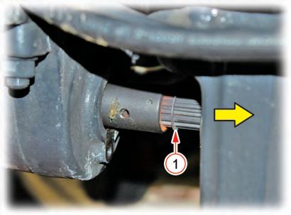
2. Pull out the propeller shaft coupling spring pin (1) from the propeller shaft cover 2 side.
4. Place a stand or hydraulic jack under the engine oil pan and remove the front wheels.
5. Unscrew the mounting bolts between the front axle support and bevel gearcase to separate the bevel gearcase assemblies (LH/RH).
• Mounting bolt tightening torque 123.6 ~ 147 N•m
12.6 ~ 15 kgf-m
91.1 ~ 108.5 ft-lb
4. Push each coupling to the propeller shaft side to remove them. Then remove the propeller shaft and cover.


