
1 minute read
HYDRAULIC SYSTEM - DISASSEMBLY, SERVICE AND ASSEMBLY


3. Undo the check valve seat (1) and pull out the check valve (2) and spring (3) in order.
5. Undo the plug (1) and remove the spring (2), unload valve (3) and plate (4).
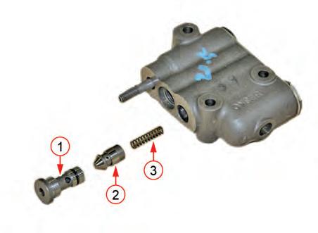
4. Unscrew the seat plug (1) and remove the poppet valve (2) and spring (3).

6. At this moment, check the O-ring at the oil flow hole that touches the hydraulic cylinder body.
7. When installing the control valve assembly, set the distance (A) between the pusher assembly (1) and joint plate (2) to 20+0 0 .2


HYDRAULIC SYSTEM - DISASSEMBLY, SERVICE AND ASSEMBLY
6.5 FLOW CONTROL VALVE
6.6 RELIEF VALVE
1. Loosen the nut (1) to remove the flow control valve assembly (2).


REMARK
• Apply a sufficient amount of grease around the O-ring and prevent any damage when installing O-ring or back-up ring.
1. Loosen the nut (1) to remove the relief valve assembly (2).

REMARK
• Apply a sufficient amount of grease around the O-ring and prevent any damage when installing O-ring or back-up ring.
HYDRAULIC SYSTEM - DISASSEMBLY, SERVICE AND ASSEMBLY
6.7 HYDRAULIC BLOCK
6.7.1. HYDRAULIC BLOCK ASSEMBLY COMPONENTS DISASSEMBLY
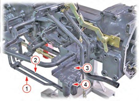
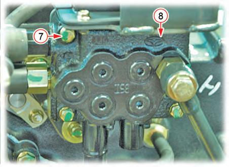
1. Disconnect the hydraulic pipes (1 and 2) and unscrew the mounting bolt (3) to remove the hydraulic block (4).


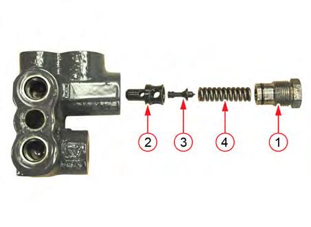
1. Unscrew the plug (1) and remove the valve seat (2), valve (3) and spring (4).
2. Pull out the snap ring (1) and remove the switch shaft (2).
HYDRAULIC SYSTEM - DISASSEMBLY, SERVICE AND ASSEMBLY
6.8 LOADER JOYSTICK VALVE
6.8.1. REMOVAL
3. Remove the plug (1).
4. Install in the reverse order of removal.
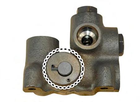
5. The dotted area on the switch shaft indicates the assembly direction (direction set at factory) for the external hydraulic connection. Turn it 90˚ when using the front loader. Adjust and assemble in same way for the opposite spring pin.

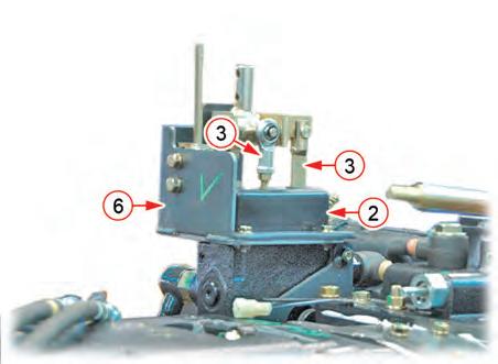
1. Remove the joystick lever (1).
2. Remove the rubber bellows (2) from the joystick lever and remove the connecting pin (4) inside to separate the joystick rod (3) and joystick valve spool.
3. 3. Unscrew the joystick support mounting screw (5) to remove the joystick support (6).
HYDRAULIC SYSTEM - DISASSEMBLY, SERVICE AND ASSEMBLY


6.8.2. DISASSEMBLY

HYDRAULIC SYSTEM - DISASSEMBLY, SERVICE AND ASSEMBLY
R69W652A
3. Unscrew the bolts and remove the cover (1).


R69W653A
4. Remove the spool (1) slowly as shown in the figure.
► ASSEMBLY
1. Install the spool.
• Check if the spool is damaged. If so, replace the valve assembly with a new one.
• Check if the O-ring is damaged.
• Apply oil to the spool and valve before installing them.
2. Install the check valve.
3. Install the main relief valve.


