1 minute read
STEERING SYSTEM - DISASSEMBLY, SERVICE AND ASSEMBLY


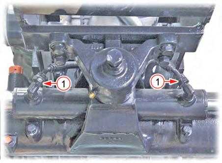
3. Remove the steering cylinder hydraulic hoses (LH/RH)(1).
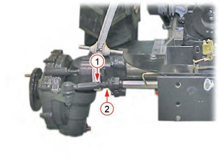
7. Install the steering cylinder again. If necessary, adjust the toe-in to the specification (2 ~ 8 mm). At this time, unscrew the mounting nut (1) of the ball joint end and turn the rack end (2) for adjustment. After adjustment, tighten the mounting nut of the ball joint end firmly.
Remark
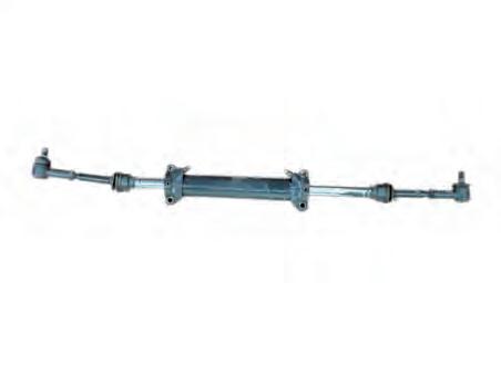
• The steering cylinder is supposed to be replaced as one unit. If oil leaks from it or it is faulty, replace it as one unit.
Remark
A03W914A
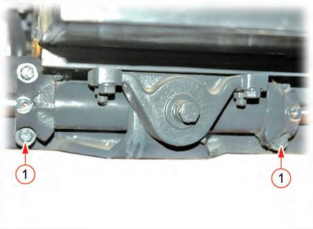
4. Unscrew the steering cylinder bracket mounting bolts (1) to remove the steering cylinder. Mounting bolt
• When installing the steering cylinder and ball joint (tie rod end), apply thread lock (LOCTITE® #271 or equivalent) to the threads and tighten them to the ����� torque.
A03W915A
5. Remove the steering cylinder assembly.
6. Assemble in the reverse order of disassembly.
Table Of Contents
1. SPECIFICATIONS
1.1 GENERAL SPECIFICATIONS
HYDRAULIC SYSTEM - SPECIFICATIONS
HYDRAULIC SYSTEM - SPECIFICATIONS
1.2 TIGHTENING TORQUE
REMARK
• Steering hose connection: PF3/8
• Steering unit elbow: PF3/8
• Steering cylinder elbow: PF1/4 coupler:
HYDRAULIC SYSTEM - STRUCTURE AND OPERATING PRINCIPLE
2. STRUCTURE AND OPERATING PRINCIPLE
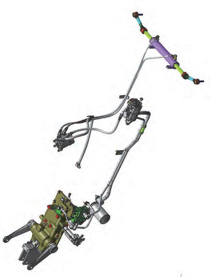
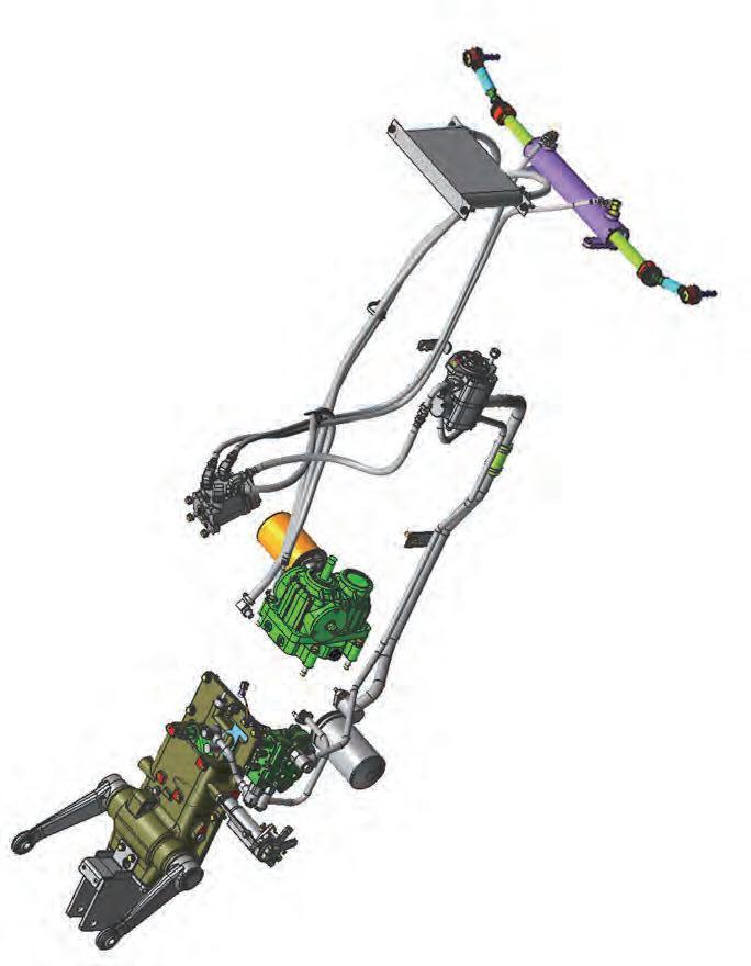
2.1 COMPONENT ARRANGEMENT
HYDRAULIC SYSTEM - STRUCTURE AND OPERATING PRINCIPLE
HYDRAULIC SYSTEM - STRUCTURE AND OPERATING PRINCIPLE
2.2 OPERATING PRINCIPLE
The hydraulic pump equipped in this tractor is a gear driven pump and the primary and secondary pumps are installed in tandem. The primary pump is a relatively small pump for the tractor operation while the secondary pump is a largecapacity pump for an implement. Therefore, the primary pump is used for the steering system, HST (HST MODEL), while the secondary pump is used for the hydraulic bolck (3510(H)-EU, TH), loader joystick valve (US, AU, 4010(H)EU), rear aux. valve, position control valve, etc.


