
4 minute read
HYDRAULIC SYSTEM - STRUCTURE AND OPERATING PRINCIPLE


2.3.6. HYDRAULIC BLOCK
Circuit And Function
A: TO ATTACHED IMPLEMENT CONTROL VALVE IN PORT

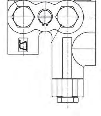
B: FROM ATTACHED IMPLEMENT CONTROL VALVE TANK PORT
C: POSITION WHEN NO IMPLEMENT IS ATTACHED
D: POSITION WHEN AN IMPLEMENT IS ATTACHED
1. The oil supplied from the secondary pump of the gear pump is drawn to the aux. hydraulic valve through the hydraulic block. The hydraulic valve has a relief valve which opens to return the hydraulic fluid to the transmission case if the pressure in the hydraulic line is excessively high (over 185 kgf/cm2, 18130 kPa, 2631 psi).
Important
• If the hydraulic power should be used for the implement, replenish the transmission fluid as much as the cylinder of the implement requires.
Remark
• Check the oil type and make sure that the oil is not contaminated before installing the implement.
(1) IN PORT PLUG
(2) OUT PORT PLUG
(3) SPOOL
(4) RELIEF VALVE

2. Also, the hydraulic block is able to supply the hydraulic power for the external implement, such as a front rotor, like the external hydraulic valve (quick coupler).
3. External implement connection
• Remove the plugs from the IN port (1) and OUT port (2) on the hydraulic block.
• Install the fluid outlet adapter (PT 3/8") to the IN and OUT ports.
• Connect the hydraulic hose to the OUT port adapter and the IN port of the implement control valve.
• Connect the other hydraulic hose to the IN port adapter and the tank (return) port of the implement control valve.
• Turn the (-) slot at the end surface of the spool (3) in order to be vertical in the arrowed direction.
Remark
• When no implement is installed, turn the (-) slot at the end surface of the spool to fix it horizontally.
HYDRAULIC SYSTEM - STRUCTURE AND OPERATING PRINCIPLE
RELIEF VALVE (HYDRAULIC BLOCK)
• If the oil pressure is below the specified pressure of the relief valve, the relief valve does not operate and the passage is formed from the gear pump to the inlet of the hydraulic cylinder.
• As the pressure in the hydraulic circuit increases, the pressure in the damping chamber D increases as well.
• If the pressure exceeds the specified value of the valve and spring tension, the valve opens to return the hydraulic fluid to the transmission case through the T1 port
• If a sufficient amount of fluid is discharged and the oil pressure drops below the specified value, the valve is closed.
HYDRAULIC SYSTEM - STRUCTURE AND OPERATING PRINCIPLE
2.3.7. LOADER JOYSTICK VALVE
The port (P) in the figure is the inlet port where hydraulic fluid flows into from the secondary hydraulic pump. The port (C) is the valve carryover line that supplies remote hydraulic valve and hydraulic cylinder with fluid if the joystick valve is not used.
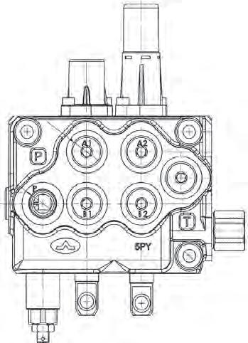

The port (T) is the return port to the transmission case. It discharges hydraulic fluid returned from the implement when the joystick valve is in operation.
26 L/min (6.87 U.S. gpm) of hydraulic fluid from the secondary gear pump is supplied to the loader joystick valve assembly. The joystick valve assembly consists of the main relief valve and two spool valves. The set pressure of the main relief valve is 185 kg/cm² (at 26 lpm). It controls the maximum pressure of the implement line. The figure upper shows the switched condition of the valves and the status of the loader operation depending on the direction of the joystick lever.
HYDRAULIC SYSTEM - STRUCTURE AND OPERATING PRINCIPLE
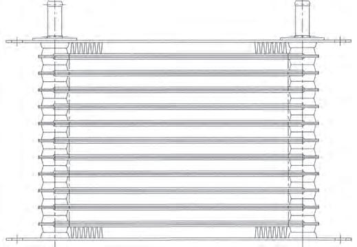
2.3.8. OIL COOLER [HST MODEL]
Oil returned from the HST filter through the steering unit passes through the oil cooler to be cooled before it is drained into the transmission.
Specifications
2.3.9.
HYDRAULIC SYSTEM - STRUCTURE AND OPERATING PRINCIPLE
HYDRAULIC LIFT CYLINDER
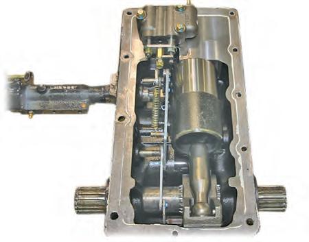
INTERNAL STRUCTURE & OPERATING PRINCIPLE
(1) POSITION CONTROL LEVER
(2) POSITION ROD
(3) ADJUST LEVER
(4) POSITION CONTROL SHAFT A
(5) POSITION CONTROL LEVER ARM
(6) VALVE CONTROL LINK
(7) POSITION CONTROL LINK
(8) POSITION FEEDBACK LINK
(9) FEEDBACK LINK A
(10) SET SHAFT
The position control system is designed to lift and lower the lift arm using the position control lever, lift control valve and feedback mechanism in order to control the position of the rear implement. The implement's position is determined by the position control lever while its lifting operation is performed by hydraulic pressure and its lowering operation is performed with the oil passage formed by its weight.
When an operator moves the position control lever, this force is transferred through the link mechanism to operate the spool of the lift control valve. However, as soon as the lever is stopped, the spool is returned to its neutral position to stop movement of the three-point hitch.
HYDRAULIC SYSTEM - STRUCTURE AND OPERATING PRINCIPLE
When moving the position control lever to the lifting position, the position control shaft A (1) turns the position control lever arm (2) clockwise. Then, the valve control link (3), which is connected to the position control lever arm, touches the pusher pin roller (4) to push the pusher (5) toward the lift control valve (6).

As the pusher is connected to the joint plate (7) of the lift control valve, it presses the joint plate which then moves the main spool into the lift control valve to open the oil passage in order to lift the lift arm.
When the lift arm (8) is lifted, the hydraulic arm (9), which is fixed to it with splines, is turned counterclockwise. As the feedback link A (10) and position feedback link (11) are connected to the hydraulic arm, they are rotated together counterclockwise, pivoting from the set shaft (12).
Also, the position control link (13) is pivoted from the position control lever arm (2) counterclockwise, separating itself from the pin roller of the pusher.
As a result, the main spool spring in the lift control valve is returned to its original position so the spool is returned back to the neutral position and the lift arm is maintained still. On the other hand, when moving the position control lever to the lowering position, the position control lever arm is rotated counterclockwise to set the valve control link and pusher pin roller apart. Then, the join plate of the lift control valve is pushed out by the tension spring (15) to open the main spool and poppet valve in order to form the oil passage for the lowering operation. The link's feedback operation for lowering the lift arm is performed reversely based on the principle of the lifting operation.


