
4 minute read
HST - MEASUREMENT AND ADJUSTMENT


4.2 HP RELIEF VALVE PRESSURE CHECK
5. Start the engine and warm up the engine until the hydraulic fluid gets warm properly. (Transmission fluid temperature: 50 ~ 60°C (122 - 140°F)).
6. Place the range shift lever in the high speed position. Then, while the brake pedal is firmly depressed, depress the HST pedal gradually to rev up the engine.
Caution
• Make sure the lock of the brake (one side) is not unlocked.
Warning
• If the tractor moves with the brake pedal depressed, it can cause an accident. Stop the test immediately and resume the test after the service.
• Never let anyone other than the driver get near the front and rear side of the tractor. Any observer can be hit by a tractor during the test and he/she can seriously get injured.
7. When the opening sound of the relief valve is heard, read the pressure. Standard (forward/reverse driving) ................. 29.4 MPa 30 kgf/cm2
4,266 psi
8. Set the gauge to the other port and repeat the above procedures.
9. If both relief pressure in forward/reverse driving is below the specified value, it is considered that the parts in the HST are worn. If only one relief pressure of forward or reverse driving is below the specified value, it is considered that the high pressure relief valve in low pressure section is stuck or the neutral valve is defective. However, the charge pressure, the amount of oil and the oil condition (dirty or aged) should be inspected beforehand.
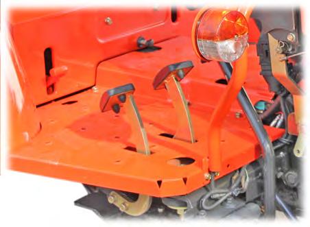
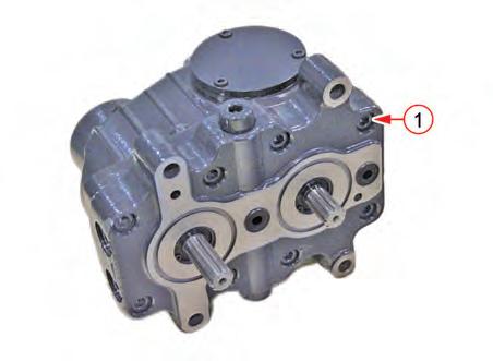
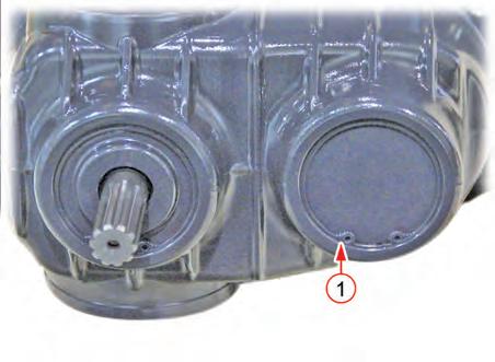
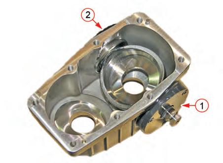
1. Remove the footstep (1) of the under the seat.
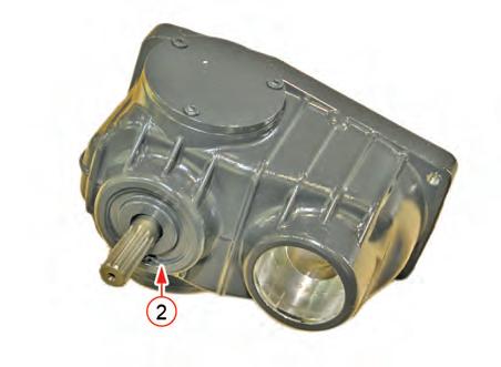
2. Disconnect the pressure gauge plug (2) of the HST through the clutch housing hole.
3. Install the adapter (PF 3/8) for pressure gauge installation to the pressure relief plug.
4. Connect the pressure gauge (400 kgf/cm2 or higher).
Important
• Do not open the relief valve for over 10 seconds to avoid the chance of oil overheating.
HST - MEASUREMENT AND ADJUSTMENT
Location Of Pressure Relief Port In Circuit
(Pressure measuring port - Reverse)
(Pressure measuring port - Forward)
HST - MEASUREMENT AND ADJUSTMENT
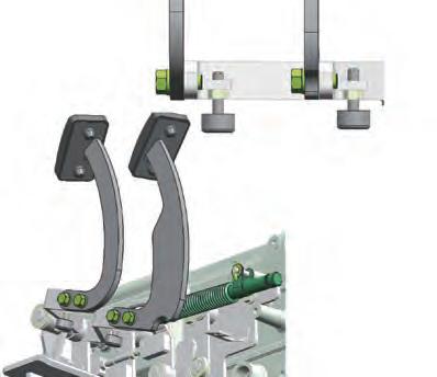
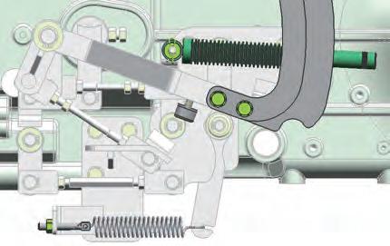
4.3 HST NEUTRAL POSITION ADJUSTMENT
4.3.1. HST PEDAL LINK ADJUSTMENT
1. Lift the rear section of the tractor with a lift to keep the rear wheels off the ground.
2. Start and run the engine at a low idle speed. Set the range shift lever in the low speed position and select 2WD operation.
Remark
3. While depressing the forward driving and reverse driving HST pedals alternately, check if the rear wheels come to a stop (neutral state) when the pedals are released.
4. If the rear wheels keep rotating, the neutral setting of the HST is not correct. In this case, adjust the length of the neutral setting control rod until the rear wheels stop.

5. To ensure correct neutral setting, repeat the above steps 3 and 4 with the range shift lever in the mid speed position.
6. To ensure correct neutral setting, repeat the above steps 3 and 4 with the range shift lever in the high speed position.
Length (L) of adjust rod for neutral setting: 152 mm (5.98 in)
4.3.2. HST PEDAL ADJUSTMENT
Setting Length Of Cushion Rubber
4.5 BLEEDING AIR FROM HST COMPONENT
• Bleed air from system before starting the engine after replacing the HST related parts, oil filters, oil and other hydraulic components. Otherwise, when the engine is started, the HST components can be damaged.
1. Disconnect the stop solenoid wiring connector.
2. Turn the key switch to run the starter motor for 5 ~ 10 seconds.
3. Connect the stop solenoid wiring again.
4. Start the engine and let the engine idle for 1 minute.
5. Lift the front wheels with a hoist and turn the steering wheel left and right until the air in the hydraulic circuit is bleeded and it rotates smoothly.
6. Set the front wheels straight ahead position and raise and lower the hydraulic lifting arm for 5 ~ 6 times. Do not apply any load onto the 3-point hitch.
7. Check the transmission fluid level and add it if necessary.
8. Raise the engine speed to approx. 1500 rpm, wait for approx. 10 seconds and drive the tractor forward and backward slowly.
9. If the tractor moves forward and backward without any problem, stop the engine and check the oil level. If the oil is insufficient, add it.
4.4 CRUISE MAGNETIC CLEARANCE ADJUSTMENT (OPTIONAL)
1. The clearance (A) between the forward driving pedal and the cruise magnetic should be set to 1 ~ 1.5 mm (0.039 ~ 0.059 in).

2. Loosen the mounting bolt of the (B) bracket and move it to the arrow direction to adjust the clearance.

HST - EXPLODED VIEW
5. EXPLODED VIEW
• The manufacturing parts are subject to change without notice. Therefore, check the parts catalog or electronic manual for latest information.
Components
COMPONENTS
5.5 CRUISE (OPTIONAL)
(2)
HST - EXPLODED VIEW
(9)
COMPONENTS
(11)
(12)
(13)
(14)
(15)
(16)
(17)
(18)
(19)
(20)
R69W621A
(21)
(22)
(23)
(24) LEVER
(25) SHAFT
(26)
(27)
6. SERVICING
1. Park the tractor on level ground, stop the engine and apply the parking brake.
2. Disconnect or remove the foot step, fender, hyadraulic pipe, link and etc. to seperate the clutch housing and transmission.

HST - SERVICING HYDRAULIC SYSTEM ELECTRIC & DIAGNOSIS
6.2. HST COMPONENTS DISASSEMBLY AND ASSEMBLY
TRANSMI SSION HST 6-26 DR72-W00
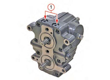
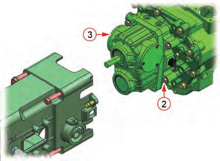
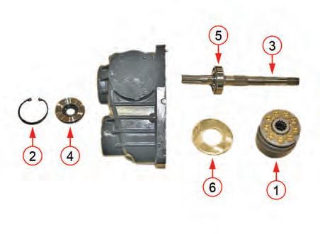
2. Unscrew the hex bolts (1) from the HST assembly to remove the port block (2) and motor cylinder block (3).

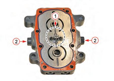
3. Remove the charge relief valve (1) and relief valve (2) of the port block.
Important
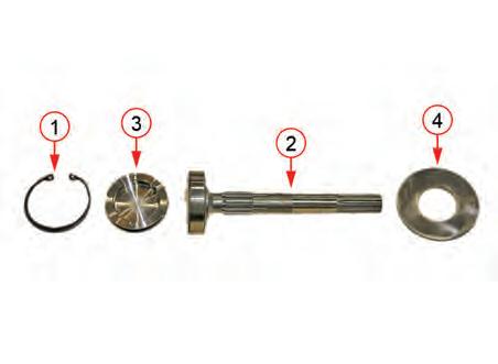
4. Remove the valve plate (1), needle bearing (2) and oil seal (3) if necessary.
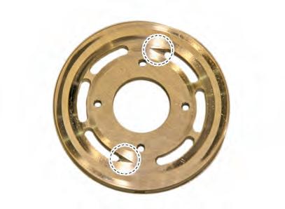
• Make sure not to mix the valve plate on the pump side (with one groove) with the valve plate on the motor side (with two grooves) during assembly.


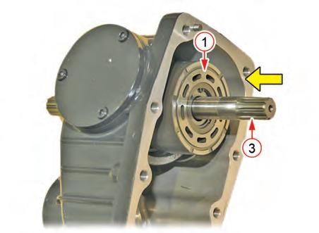
8. Remove the upper cover (1) and lower cover (2) on the piston pump side of the pump cylinder block. Then, remove the control shaft (3).

9. Install in the reverse order of removal.
• When removing the shaft, replace the oil seal with a new one. If the O-ring is defective, replace it with a new one as well. When installing the O-ring or oil seal, apply a proper amount of grease or oil to the mating surface.


