
9 minute read
ELECTRIC SYSTEM AND DIAGNOSIS - ELECTRIC COMPONENTS


4.16.2. WATER-IN-FUEL SENSOR
The crankshaft wheel sensor is a magnetic pick-up type and it is supplied with 5 V power. It outputs sine waveform according to the change in magnetic field occurred by rotation of the crankshaft. Then, the position/ speed of the crankshaft can be determined by the current value through the changed resistance value.
The crankshaft wheel sensor detects the position of each piston and sends this information to the ECU which then uses this information to set the injection timing and amount.
The water-in-fuel sensor is installed under the fuel-filter. When water enters the engine fuel system, it can damage the high-pressure fuel pump, filter and injector and cause poor engine starting performance and malfunction. Therefore, when water is collected (45cc or more) on the bottom of the fuel-filter, this water-in-fuel sensor sends a signal to the instrument cluster which then turns on the water-in-fuel warning lamp. Make sure to drain water from the fuel-filter in this case.
The crankshaft wheel sensor is a magnetic pick-up type and it is supplied with 5 V power. It outputs sine waveform according to the change in magnetic field occurred by rotation of the crankshaft. Then, the position/ speed of the crankshaft can be determined by the current value through the changed resistance value.
The crankshaft wheel sensor detects the position of each piston to determine the injection timing and amount. This sensor is a magnetic pickup type so its N polar and S polar intersect during rotation of the crankshaft to send 60 signals in total. It detects the position of each cylinder by detecting the position without a tooth on the gear.

ELECTRIC SYSTEM AND DIAGNOSIS - ELECTRIC COMPONENTS
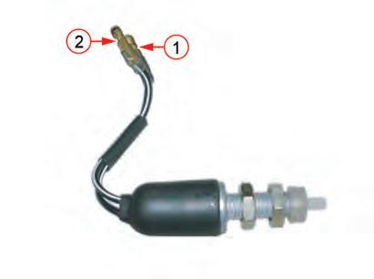
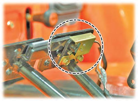
4.17 BRAKE SWITCH
The brake switch is installed to the brake pedal link and presses the switch contact point when the pedal is free. The brake switch turns on the brake lamps on the fender when the brake pedal is depressed.
• N.C (Normally Closed) Type: It is normally closed (ON) but it is open (OFF) when contact point is pressed.
ITEM
RED
LEAD BLACK LEAD
When measuring resistance, red and black tester leads can be interchangeable.
ELECTRIC SYSTEM AND DIAGNOSIS - ELECTRIC COMPONENTS
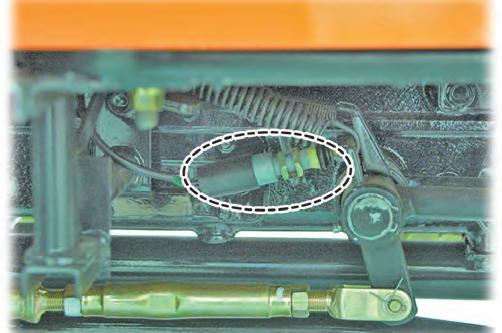
4.18 PARKING BRAKE MICRO SWITCH
4.19 SAFETY START SWITCH
This micro switch is attached to the parking brake inner side of the right step. It turns on the warning lamp on the instrument cluster when the parking brake is applied.
• N.C (normally closed) type:
It is normally closed (ON) but it is open (OFF) when contact point is pressed.
TEST
ITEM
Resistance
TESTER CONNECTIONS RESULT REMARKS
RED LEAD BLACK LEAD
Connector No, 1 Connector No, 2
Connector No, 1 Connector No, 2
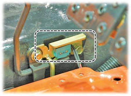
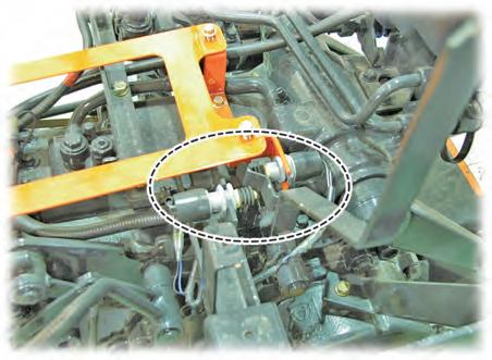
The safety start switch is installed to the clutch pedal bracket which is under side of the left step. The safety start switch is to prevent the engine from starting while the clutch is engaged.
• N.O. (Normally Open) type:
It is normally open (OFF). But when the switch contact is pressed, it becomes closed (ON).
TEST
No operation (ON) Continuity
In operation (OFF)
No continuity
When measuring the resistance with a tester, it is OK to switch the leads (red and black).
ITEM
Resistance
TESTER CONNECTION
RED LEAD BLACK LEAD
Connector No. 1 Connector No. 2
RESULT REMARKS
When not depressed (OFF)
No continuity
Connector No. 1 Connector No. 2 ON Continuity
When measuring resistance, red and black tester leads can be interchangeable.
ELECTRIC SYSTEM AND DIAGNOSIS - ELECTRIC COMPONENTS
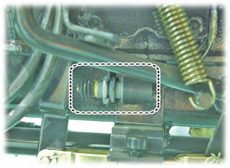
4.20 ONE SIDE BRAKE SWITCH
The brake (one side) switch is installed to the side of the connecting bracket between the brake pedals. When only one brake pedal is depressed, the brake (one side) indicator on the instrument cluster comes on.
• N.O. (Normally Open) type:
It is normally open (OFF). But when the switch contact is pressed, it becomes closed (ON).
• Connector
ELECTRIC SYSTEM AND DIAGNOSIS - ELECTRIC COMPONENTS
4.21 PTO SAFETY SWITCH
4.22 SWITCHS
4.22.1. CRUISE SWITCH [HST MODEL: OPTIONAL]
The PTO safety switch is installed on PTO lever. If the PTO 1st or PTO 2nd is shifted, this switch turns ON to prevent the starting.
When the PTO lever is shifted, the switch contact is pressed and ignition power is cut off to prevent the engine from starting.
• AU : 1EA
• TH : 2EA
• N.O. (Normally Open) type: It is normally open (OFF). But when the switch contact is pressed, it becomes closed (ON). TEST
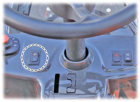
The cruise switch is installed on the left side of the dashboard.
The cruise switch has ON and OFF positions.
When pressing the upper side of the cruise switch, the switch's ON contact sends a signal to the cruise unit and the switch is locked.
When pressing the lower side of the cruise switch, the switch's OFF contact sends a signal to the cruise unit and the switch returns to the original position.
To activate the cruise control function, set the desired speed and press the switch to the “ON” position. Depress the HST pedal to increase the driving speed in order to accelerate at a constant speed. To deactivate the cruise function, depress the brake pedal or press the switch to the “OFF” position.
The cruise function is not activated during reverse.
When measuring resistance, red and black tester leads can be interchangeable.
REMARK
PTO SAFETY SWITCH INSTALLATION SETTING
• With the PTO lever shifted, set the knob rod of the PTO safety switch which is depressed for approx. 4 ~ 5 mm. Then, tighten the switch nut ���.
Switch operation:
• OFF
• Cruise connection (ON)
RANGE OPERATION
ELECTRIC SYSTEM AND DIAGNOSIS - ELECTRIC COMPONENTS
4.22.2. LINKED PEDAL SWITCH
TESTER'S MEASURING POINT RESULT RED LEAD BLACK LEAD
OFF No.1 connector No.3 connector Continuity ON No.1 connector No.2 connector Continuity
• When measuring the resistance with a tester, it is OK to switch over the leads (red and black).
If the test results are not as outlined above, replace the cruise switch.
This switch is to link HST pedal with engine rpm. Engine rpm goes up as much as HST pedal is pressed.
ELECTRIC SYSTEM AND DIAGNOSIS - ELECTRIC COMPONENTS
4.23 PREHEAT CONTROLLER
R72WC14A
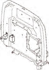
The preheat controller is installed on the shut plate in the rear right section of the engine compartment. When the preheat controller receives key ON signal or ST signal, it operates auto-preheat through the glow relay and gives the signal to instrument panel to illuminate the glow lamp.
Connector
1
2
3
R76WB12A
Connector
ELECTRIC SYSTEM AND DIAGNOSIS - ELECTRIC COMPONENTS
ELECTRIC SYSTEM AND DIAGNOSIS - ELECTRIC COMPONENTS
INPUT/OUTPUT CONTROL
• Switch Input condition : “ON” is +12V, “OFF” is open
• Sensor Input condition : “ON” → Neutral, “OFF” → Not Neutral
ELECTRIC SYSTEM AND DIAGNOSIS - ELECTRIC COMPONENTS
Preheating Function
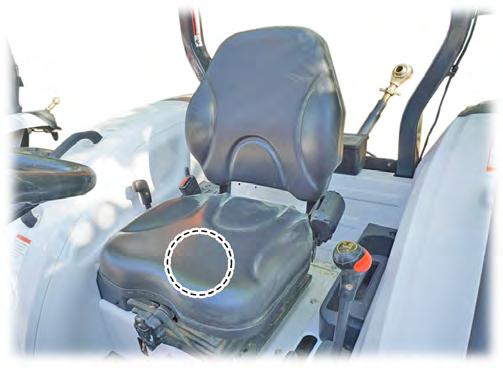
4.24 SEAT SWITCH
ELECTRIC SYSTEM AND DIAGNOSIS - ELECTRIC COMPONENTS
The seat switch is mounted inside of the seat bottom. When the driver is seated or not seated on the seat, the switch plunger is actuated to start the engine or to stop the engine. In addition, the engine stops automatically when the driver is not seated on the seat and it exceeds 3 seconds during driving.


Connect the tester (ohmmeter) to the two terminals of the seat switch and check the continuity by pressing the plunger. If the plunger does not conduct when it is pressed, or conduction occurs when does not press the plunger, there is a problem with the seat switch. Replace the seat switch with a new one.
Electric
SYSTEM AND DIAGNOSIS - ELECTRIC COMPONENTS
4.25 INSTRUMENT PANEL
4.25.1. SYBOMLS AND COMPONENTS
4.25.2. CONNECTOR
ELECTRIC SYSTEM AND DIAGNOSIS - ELECTRIC COMPONENTS
•
ELECTRIC SYSTEM AND DIAGNOSIS - ELECTRIC COMPONENTS
4.25.3. GAUGES AND INDICATORS
TACHOMETER (RPM)
R52WB69B
► ENGINE 3F-TM(H)4 MODEL
This indicates the engine rpm and the PTO rpm and is operated by ECU signal.
► ENGINE 3B183/3A165 MODEL
This indicates the engine rpm and the PTO rpm and is operated by the pickup sensor installed on the engine gearcase.
• Indication specification (unit: rpm)
• Signal specification
• Signal (CAN)
Sine wave over 1.5 Vp-p inputted at 450 Hz
Fuel Gauge
ELECTRIC SYSTEM AND DIAGNOSIS - ELECTRIC COMPONENTS
The fuel gauge's pointer indicates the resistance value corresponding to the float position which is received from the fuel sender in the fuel tank. To inspect the fuel sender, it should be removed from the fuel tank beforehand. Also, the power supplied to it and the resistance should be checked referring to the electrical circuit diagram. If the supplied power and the output resistance values are normal, the float measuring the amount of fuel may be malfunctioning. In this case, replace the fuel sender.
This gauge displays the engine coolant temperature.
If the gauge blinks under the high-temperature condition, find and check its cause and never operate the tractor. [Hot: warning lamp blinking at every second (for 5 seconds at 110°C (230°F))
If the resistance by the value of the coolant temperature sensor is within the specified range, check the thermostat, water pump and the coolant line related to the radiator for their operation and wiring and connector for proper connection.
• Tolerance and resistance value by indicating angle
ELECTRIC SYSTEM AND DIAGNOSIS - ELECTRIC COMPONENTS
Preheat Indicator
This comes on for 8 seconds when the ignition switch is turned to the "ON" position.
In cold conditions, keep the ignition switch in the "ON" position until the preheat lamp goes out. During this period of time, the glow plugs warm up the combustion chambers so that the engine is started easier.
However, the preheat lamp does not operate if the coolant temperature sensor detects the temperature of over 30°C (86°F).
TURN SIGNAL LAMPS (LH, RH)
The turn signal lamp indicator comes on in the instrument panel when operating the turn signal lamp switch.
Measuring with the ignition switch ON
PARKING
This indicator indicates the ON and OFF status of the parking brake. When the parking brake is in operation, this indicator comes on. When the parking brake is not operated, this indicator goes off.
Measuring after operating the turn signal lamps with the ignition switch in ON or OFF position
ELECTRIC SYSTEM AND DIAGNOSIS - ELECTRIC COMPONENTS
Engine Oil Warning Lamp
This indicator comes on when the engine oil pressure is too low.
This indicator comes on when initially turning the ignition switch to "ON" position and it goes off when turning the ignition switch to "ST" position.
If this indicator comes on while driving, stop the engine immediately and check the engine oil level.
BRAKE (ONE SIDE) INDICATOR
This indicates the ON and OFF status of the brake (one side). When the brake (one side) is not in operation, this indicator comes on. When the brake (one side) is released, this indicator goes off.
This indicator comes on when turning the ignition switch to "ON" position and it goes off when turning the ignition switch to "ST" position. If this indicator comes on while driving, the charging system is malfunctioning. Check the charging system immediately.
Measuring with the ignition switch ON
CHECK
The check engine warning lamp on the instrument cluster comes on when the engine fuel system or major electric component is malfunctioning. In this case, the engine may stall in approx. one minute after the engine power is reduced or the engine RPM is fixed. This is to inform the driver the current problem in the vehicle and let him/her take an appropriate action immediately
When this warning lamp is illuminated, make sure to stop the engine have the engine checked immediately.
ELECTRIC SYSTEM AND DIAGNOSIS - ELECTRIC COMPONENTS
WATER-IN-FUEL WARNING LAMP
When a certain amount of water (approx. 45 cc) is accumulated in the fuel filter, this warning lamp on the instrument cluster comes on and the engine power is reduced.
In this case, water in the fuel filter should be drained immediately.
It is recommended to drain water from the filter when changing engine oil in the maintenance schedule.
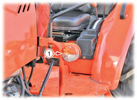
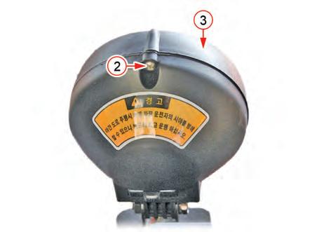
Bulb Replacement
1. Open the hood.
2. Disconnect the headlamp connector (2).

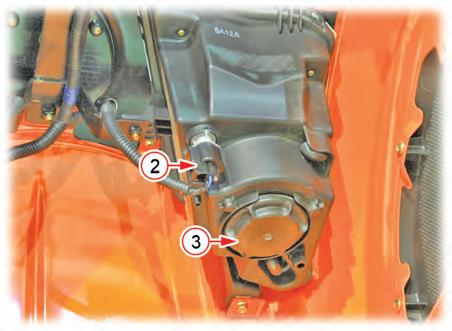

3. Turn the cap (3) counterclockwise to remove it.
4.26 LAMPS
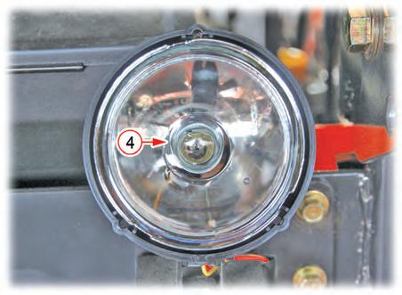
4. Disconnect the bulb connector (4) and press the spring (5) to release the bulb.
5. Remove the bulb and replace it with a new one. Install a new bulb in the reverse order or removal.
• Bulb specification: 12V 55W

ELECTRIC SYSTEM AND DIAGNOSIS - ELECTRIC COMPONENTS
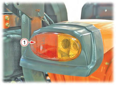
4.26.2. FRONT COMBINATION LAMP
4.26.3. WORK LAMP
BULB REPLACEMENT
2. Remove the bulb (4) by pressing and turning it. (Turn signal lamp)

3. Remove the bulb (5) by pushing it to one side. (Tail lamp)

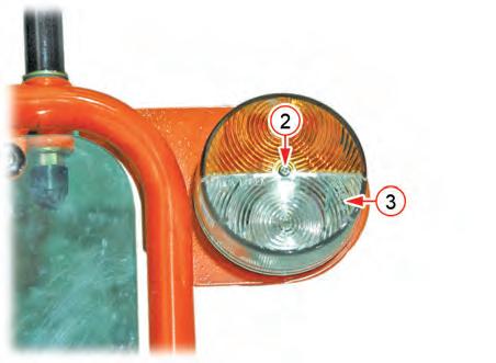
4. Replace the bulb with a new one as necessary.
• Bulb specification: 12 V 21 W (turn signal lamp) 12 V 10 W (tail lamp)
The
BULB REPLACEMENT
2. Remove the bulb (4) by pressing and turning it and replace the bulb with a new one.
• Bulb specification: 12V-P21/5W
ELECTRIC SYSTEM AND DIAGNOSIS - ELECTRIC COMPONENTS
4.26.4. REAR COMBINATION LAMP


3. Turn the bulb socket (6) counterclockwise to remove it.
5. Replace the bulb with a new one as necessary.
• Bulb specification: 12 V 21 W (turn signal lamp) 12 V 21 W/5 W (brake / tail lamp)

ELECTRIC SYSTEM AND DIAGNOSIS - TROUBLESHOOTING
5. TROUBLESHOOTING
5.1 WHEN THE ENGINE CANNOT BE STARTED
1. Check the battery voltage
- Measure the voltage between battery (+) and (-) terminals using a tester
Result: 11.8 ~ 12.9 V. However, the voltage may be over this range if it is measured immediately after turning the engine off.
2. Battery terminal of start motor


1. Check the battery cable connection.
- The voltage between the terminal M of start motor and chassis should be approximately same to the battery voltage.
- Check for corrosion.
2. Checking when voltage is not supplied
- Check the battery cable connection.
3. Slow-blow fuse
1. Fuse engagement
2. Check the main fuse for short circuit. Rated capacity: 60 A
4. Ignition switch
- Check for proper connection
“OFF” position: No connection
“ACC” position: A-B
“ON” position: A-B-D
"PREHEAT" position: A-C-D
"ST" position: A-D-E
A - BATTERY
B - ACCESSORY (ACC)
C -ENGINE PREHEAT (G)
D - IGNITION SWITCH ON
E - IGNITION (ST)
AC B DE T85WBD8A
Check Point
5. Starter relay


