5 minute read
HYDRAULIC SYSTEM - STRUCTURE AND OPERATING PRINCIPLE


2.3 COMPONENTS
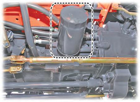
2.3.1. HYDRAULIC FILTER
2.3.2. HST FILTER
(1) CARTRIDGE PACKING
(2) ELEMENT PACKING
(3) CARTRIDGE BODY
(4) ELEMENT SPRING
(5) FILTER ELEMENT
(6) CARTRIDGE CAP
R69WB17A
(7) CARTRIDGE PLATE
(8) ELEMENT CAP (TOP)
(9) ELEMENT CAP (BOTTOM)
(10) ELEMENT INNER CORE
The hydraulic filter (1) is installed on the suction line in front of the gear pump. Oil drawn into the filter passes from the outside to the inside of the filter element.
The filter element is a net type which is not reusable nor washable.
• Replacement interval: 50 hours after initial operation, and then every 200 hours of operation
ELEMENT SPECIFICATIONS (1 EA)
(1) CARTRIDGE BODY
(2) CAP
(3) ELEMENT PACKING
(4) SCREW PLATE
(5) FILTER ELEMENT
(6) CARTRIDGE PACKING
(7) SPRING
The HST filter is installed on the left side of the transmission under the floor, and it is connected to the port T of the steering unit. As carryovered oil flows from the outside to the inside of the filter element, its foreign material is separated.
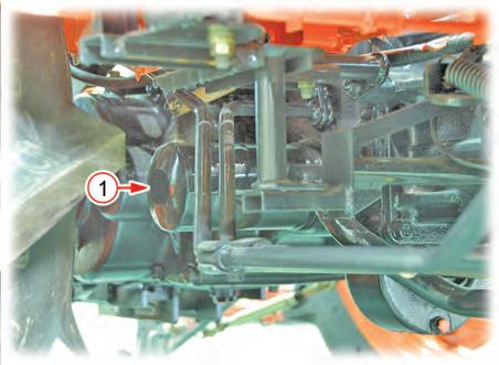
• Replacement interval: 50 hours after initial operation, and then every 200 hours of operation ITEM
FILTER PAPER SPECIFICATIONS
Bursting strength 1.96 bar
Filtering dimension 3,094 cm2 ± 10%
Number of folds 65
HYDRAULIC SYSTEM - STRUCTURE AND OPERATING PRINCIPLE
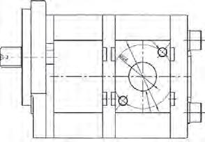
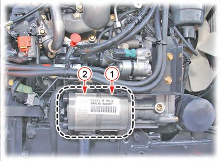
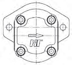
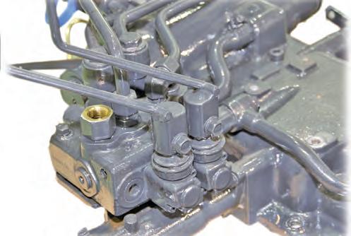
2.3.3. GEAR PUMP
The gear pump is installed as one unit in tandem. It is driven by the engine crankshaft gear at the ratio of 1:1, so its rotating speed is the same to the one of the engine crankshaft. The primary pump supplies oil to the steering unit, HST (HST MODEL) while the secondary pump supplies oil to the hydraulic bolck (3510(H)-EU, TH), joystick valve (US, AU, 4010(H)-EU), rear aux. valve, lift control valve.
Hydraulic Pump Specifications
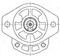
Engine rated speed - 2,600 rpm
Speed ratio of engine and gear pump - 1 : 1
PUMP
The capacity of the primary pump is 6.5 cc/rev. This means that this pump supplies 6.5 cc of oil per revolution. When the engine is running at the rated rpm (2,600 rpm), the amount of oil supplied per minute is as follows:
Primary pump: 6.5 cc x 2,600 rpm ÷ 1,000 = 16.9 L/min (4.46 U.S. gpm). With the same method, as the capacity of the secondary pump is 10 cc/rev.
Secondary pump: 10 cc x 2,600 ÷ 1,000 = 26 L/min (6.87 U.S. gpm).
HYDRAULIC SYSTEM - STRUCTURE AND OPERATING PRINCIPLE
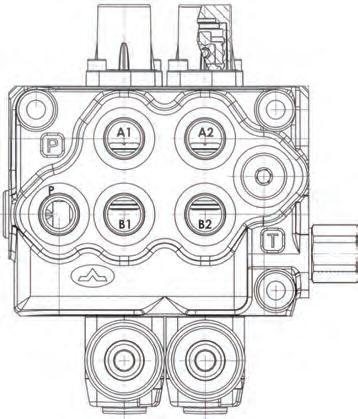
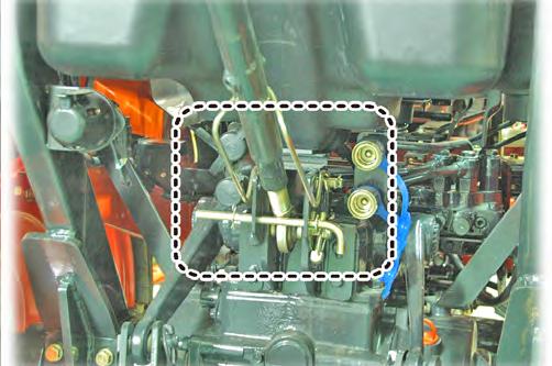
2.3.4. REAR AUX. VALVE (REMOTE HYDRAULIC VALVE)
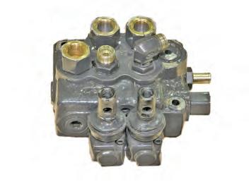
The system is equipped with two remote hydraulic valves. These valves are typical double acting valves and cannot be operated simultaneously. Also, a check valve is integrated in each valve to prevent a back flow in order to protect the circuit. The rear auxiliary valve is a double acting valve of either a standard type or detent type. For a standard type, when the lever is moved and released, the lever is returned to the neutral position automatically. However, for the detent type, when the lever is moved to a certain position and is released, the lever stays in that position and this feature can be useful for an implement with a motor that needs continuous oil supply.
HYDRAULIC SYSTEM - STRUCTURE AND OPERATING PRINCIPLE
Caution
• If the double acting valve is used for the single acting cylinder, the main relief valve opens in the cylinder retraction operation, so frequent use of it can increase the hydraulic oil temperature excessively
• Therefore, it is recommended to avoid using an implement that requires to use the single acting cylinder frequently for an extended period of time
This valve is a double acting valve, but it can be used in the single acting cylinder.
When the hose of the single acting cylinder is installed to the rear quick coupler (only one), this valve operates as an single acting valve.
In this case, if the spool operating direction of the valve is same to the fluid flow direction to the connected coupler, the cylinder is correctly expanded. If the spool operating direction is reversed, the pressure in the hose rises since no hose is connected to the quick coupler. Then, the main relief valve opens and the fluid from the pump is drained to the transmission. As the single acting cylinder is lowered by the outer load, the fluid in the cylinder flows to the transmission through the drain spool of the valve.
HYDRAULIC SYSTEM - STRUCTURE AND OPERATING PRINCIPLE
2.3.5. LIFT CONTROL VALVE (PCV VALVE)
Structure And Function
(1) VALVE BODY
(2) UNLOAD VALVE
(3) SPOOL
(4) CHECK VALVE
(5) POPPET VALVE
(C) PORT ON HYDRAULIC CYLINDER SIDE
(P) PORT ON HYDRAULIC PUMP SIDE
The lift control valve is integrated in the hydraulic lift cylinder case, and it mainly consists of the spool, check valve, unload valve and poppet valve. The spool is operated by the link in the hydraulic lift cylinder case. Oil supplied from the hydraulic pump is led through the port P and is delivered to the hydraulic cylinder through the port C.
The spool is pushed in for 8 mm (0.31 in) from the neutral position toward the lift control valve for lifting operation while it is pushed out for 8 mm (0.31 in) from the neutral position toward the opposite side for lowering operation. When the position control lever is moved to the lifting or lowering position, this spool is moved to send hydraulic oil to the hydraulic cylinder or transmission case. The poppet valve (5) is opened only when lowering the implement in order to drain hydraulic oil in the hydraulic cylinder to the transmission case. The check valve (4) prevents hydraulic oil in the hydraulic cylinder from flowing backward.
HYDRAULIC SYSTEM - STRUCTURE AND OPERATING PRINCIPLE
1. 1. Hydraulic oil delivered from the hydraulic pump is led into the lift control valve through the port P.
2. 2. Supplied oil flows along the side passage to open the unload valve (1). Then, it is drained to the transmission case.
3. 3. Oil behind the unload valve (1) is drained to the transmission case through the spool (2).
4. 4. Oil in the hydraulic cylinder is kept still as the check valve (3) and poppet valve (4) are closed. Therefore, the implement is maintained at a certain height.
1. 1. When placing the position control lever to the lifting position, the spool (1) is pushed in the arrow direction to open two oil passages led to the unload valve.
2. 2. Oil delivered from the hydraulic pump is led into both passaged on the unload valve side through the port P.
3. 3. As the diameter of the oil passage on the side A is smaller than the diameter of the on on the side B, pressure on the side A is higher than pressure on the side B with the same amount of oil flow. Therefore, the unload valve (2) is closed.
4. 4. As a result, oil opens the check valve (3) and it is supplied to the hydraulic cylinder through the port C to push up the piston in order to lift the implement.
HYDRAULIC SYSTEM - STRUCTURE AND OPERATING PRINCIPLE
1. When placing the position control lever to the lowering position, the spool (1) is pushed out. As the poppet valve (2) is also fixed to the spool with the joint plate (3), it is pushed out as well.
2. Therefore, the passage A, which is connected to the unload valve, is closed while the passage B is open.
3. Oil supplied through the port P flows through the passage B to open the unload valve (4). Then, it is drained to the transmission.
4. Oil in the hydraulic cylinder is led to the poppet valve (2) through the port C by weight of the implement. Then, it is drained to the transmission through the opening of the poppet valve, resulting in lowering of the implement.


