2 minute read
FRONT AXLE - DISASSEMBLY, SERVICE AND ASSEMBLY


Remark
6. Support the front axle support with a hydraulic jack or hoist. Unscrew the front bracket mounting bolts (1) and rear bracket nuts (2) to separate the front axle assembly from the main body.
• Mounting bolt, nut tightening torque ......... 123.6 ~ 147 N•m 12.6 ~ 15 kgf-m 91.1 ~ 108.5 ft-lb
• When removing the rear bracket, be careful not to miss the thrust collar (1) and O-ring (2) in it.
7. Support the front axle support with a hoist in a safe place. If necessary, separate the front bracket (1) and rear bracket (2).


• When installing the DX bushing in the rear bracket, align the greasing hole with the bushing hole.


• When removing the front bracket, be careful not to miss the adjusting plate in it. Also, when installing the DX bushing in the front bracket, align the grease nipple mounting hold with the bushing hole.

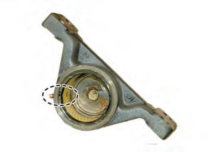
10. Pull out the snap ring (1) and remove the front differential system assembly (2) and shim (3) together.


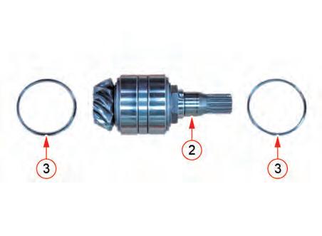
11. If necessary, undo caulking of the mounting nut (1) from the bevel pinion shaft unit to unscrew the nut. Then, remove the taper roller bearing (2) and spacer (3).
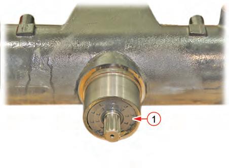


12. Assemble in the reverse order of disassembly.
Installation For Bevel Pinion Shaft
1. Stand the spiral bevel pinion shaft as shown in the figure and install the inner taper roller bearing.
IMPORTANT
• Be careful with the direction of the taper roller bearing.
2. Install the outer cup of the 1st taper roller bearing.
3. Put the spacer to the outer cup of the inner taper roller bearing.
4. Put the outer cup of the outer taper roller bearing on the spacer.
5. Install the second taper roller bearing to the pinion shaft by engaging it with the shaft.
6. Tighten the new lock nut slightly.
IMPORTANT
• Be careful with the direction of the taper roller bearing.
FRONT AXLE - DISASSEMBLY, SERVICE AND ASSEMBLY
7. Insert the inner adjusting collar (1) into the housing.
8. Insert the pinion shaft (2) with the taper roller bearing and the locking nut into the housing.
9. Install the outer adjusting collar (3) and then the snap ring (4).
10. Tighten the locking nut (5) so that the proper amount of preload is applied to the taper roller bearing.
11. Check the preload of the taper roller bearing is correct by measuring the turning torque of the pinion shaft. (Refer to section 4. INSPECTION AND ADJUSTMENT)
12. When the preload of the taper roller bearing is determined, lock the locking nut so that it is not loosened.
13. Insert the differential assembly (7) with the 21 spiral bevel gear (6) and the bearing into the left side of the axle support housing (8). Make sure the 21 gear faces inner side.
14. Insert the shim (9) and install the snap ring (10).
15. Measure the backlash and the contact area of the spiral bevel pinion and 21 spiral bevel gear.
16. Insert the new oil seal (11) into the spiral bevel pinion shaft.
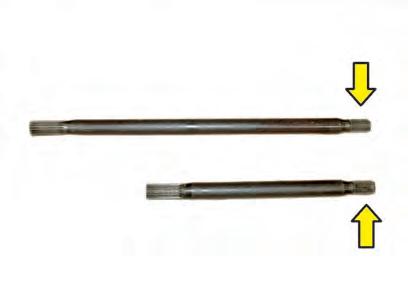
• When installing the differential pinion shaft, its longer spline should be mounted