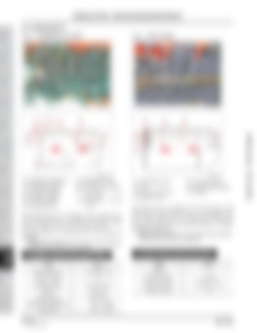
2.3 COMPONENTS 2.3.1. HYDRAULIC FILTER
2.3.2. HST FILTER
TRANSMI SSION TRANSMISSION
R69WB16A
1
7
8
3
2
5
4 10
REAR BRAKE AXLE FRONT BRAKE AXLE STEERING SYSTEM FRONT AXLE HYDRAULIC STEERING SYSTEM HYDRAULIC ELECTRIC & DIAGNOSIS SYSTEM A/C AND INDEX HEATER
1
5
7
6 3
9 4
REAR HSTAXLE
TRANSMI SSION HST
6 2
R69WB33A
R69WB17A
(1) CARTRIDGE PACKING (2) ELEMENT PACKING (3) CARTRIDGE BODY (4) ELEMENT SPRING (5) FILTER ELEMENT (6) CARTRIDGE CAP
(7) CARTRIDGE PLATE (8) ELEMENT CAP (TOP) (9) E L E M E N T C A P (BOTTOM) (10) E L E M E N T I N N E R CORE
The hydraulic filter (1) is installed on the suction line in front of the gear pump. Oil drawn into the filter passes from the outside to the inside of the filter element. The filter element is a net type which is not reusable nor washable. • Replacement interval: 50 hours after initial operation, and then every 200 hours of operation
ELEMENT SPECIFICATIONS (1 EA)
R69WB18A
(1) CARTRIDGE BODY (2) CAP (3) ELEMENT PACKING (4) SCREW PLATE
(5) FILTER ELEMENT (6) CARTRIDGE PACKING (7) SPRING
The HST filter is installed on the left side of the transmission under the floor, and it is connected to the port T of the steering unit. As carryovered oil flows from the outside to the inside of the filter element, its foreign material is separated. • Replacement interval: 50 hours after initial operation, and then every 200 hours of operation
FILTER PAPER SPECIFICATIONS
ITEM
SPEC
ITEM
Filtering dimension
1,078 cm2 ± 10%
Material
Number of folds
70
Bursting strength
1.96 bar
Bursting strength
4.5 bar or more
Filtering dimension
3,094 cm2 ± 10%
Material
SUS-NET
Number of folds
65
Filtering density
150 +-73 mesh
Range of the operational oil temperature
11-10294 of 450
SPEC
-20°C ~ +90°C (-4°F ~ 194°F)
DR72-W00
Dealer Copy -- Not for Resale
CLUTCH
ENGINE
GENERAL
SAFETY FIRST
HYDRAULIC SYSTEM - STRUCTURE AND OPERATING PRINCIPLE


