Bobcat CT2035 2000 Series Compact Tractor Service Manual 7398896 (12-19)

Page 292

2.2.2. IMPLEMENT SECTION Hyd. Block Ass'y [3510(H)-EU, TH]

GENERAL

SAFETY FIRST

HYDRAULIC SYSTEM - STRUCTURE AND OPERATING PRINCIPLE

NJI FP

ENGINE

3

6 4

*HDU UDWLR

$ %

%220

%8&.(7

$ %

2

+\G )LOWHU

6

Loader Joystick Valve Ass'y [US, AU, 4010(H)-EU]

Rear Aux. Valve Ass'y 'RZQ 6SHHG &RQWURO 9DOYH

REAR HSTAXLE

Position Control Valve

5

8QORDG 9DOYH

Dealer Copy -- Not for Resale

3

&\OLQGHU

&UDQNLQJ NJI FP

3RSSHW 9DOYH

6SRRO

REAR BRAKE AXLE

$ %

OSP NJI FP

OSP

1

$ % *HDU SXPS

FF UHY FF UHY

(1*,1(

TRANSMI SSION HST

TRANSMI SSION TRANSMISSION

CLUTCH

Steering unit

6DIHW\ 5HOLHI

A/C AND INDEX HEATER

HYDRAULIC ELECTRIC & DIAGNOSIS SYSTEM

HYDRAULIC STEERING SYSTEM

STEERING SYSTEM FRONT AXLE

FRONT BRAKE AXLE

R72WB16B

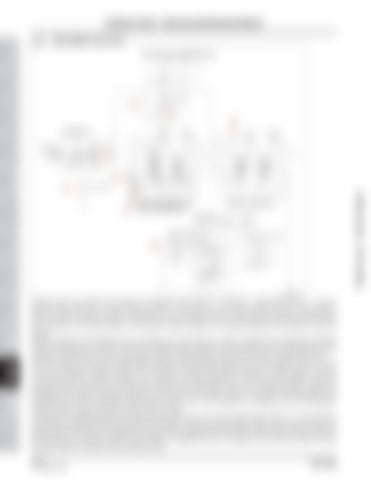
Hydraulic fluid in the implement line flows in the following order: filter (1) → pump (2) → main relief valve (6) → hydraulic block (3), joystick valve (3) → remote hydraulic valve (4) → lift control valve (5). If hydraulic fluid is used in a certain step, it cannot be used in the following step. For example, the remote hydraulic valve and lift cylinder cannot be used at the same time. Therefore, the remote hydraulic valve should be firstly checked if it is properly operated if the lifting arm does not operate. Hydraulic pressure of the implement line is controlled by the main relief valve, which is installed to the hydraulic block (joystick valve), to 185 kgf/cm² (18,130 kPa / 2,631 psi). Therefore, when pressure in the circuit rises over the relief pressure due to overload for the operation of the remote hydraulic valve and lifting cylinder, the relief valve is open to protect the circuit. When the engine is running at the rated speed (2,600 rpm), the secondary gear pump with the capacity of 26 L/min (6.87 U.S. gal) is operated to supply hydraulic oil to the loader hydraulic block (joystick valve) (3), remote hydraulic valve (4) and lift control valve (5) mainly for tractor work. Hydraulic oil is firstly supplied to the hydraulic block (joystick valve) after passing through the oil filter and secondary gear pump from the transmission case. Then, for loader operation, hydraulic oil is supplied to the loader through the outlet port. Oil returned from the loader cylinder is led back to the transmission case through this port. When the hydraulic block (joystick valve) is not in use, hydraulic oil is supplied to the next component, remote hydraulic valve, through the carryover line in the valve. The above circuit diagram shows two double acting valves. If any one of two double acting valves is in use, the threepoint hydraulic cylinder behind this step cannot be operated. When the remote hydraulic valve is not in use, hydraulic oil is supplied to the lift control valve through the carryover line to operate the three-point link. When lifting the lift arm, hydraulic oil is supplied to the hydraulic cylinder. When lowering or stopping the lift arm, oil supplied to the valve and drained from the hydraulic cylinder is returned to the transmission case.

11-8292 of 450

DR72-W00


Turn static files into dynamic content formats.

Create a flipbook

Articles inside

ELECTRIC SYSTEM AND DIAGNOSIS -

1min
pages 434-436

ELECTRIC SYSTEM AND DIAGNOSIS - ELECTRIC COMPONENTS

9min
pages 374-396

HYDRAULIC SYSTEM - DISASSEMBLY, SERVICE AND ASSEMBLY

1min
pages 332-337

HYDRAULIC SYSTEM - DISASSEMBLY, SERVICE AND ASSEMBLY

1min
pages 329-331

HYDRAULIC SYSTEM - DISASSEMBLY, SERVICE AND ASSEMBLY

2min
pages 324-328

HYDRAULIC SYSTEM - STRUCTURE AND OPERATING PRINCIPLE

4min
pages 301-306

HYDRAULIC SYSTEM - STRUCTURE AND OPERATING PRINCIPLE

5min
pages 294-300

HYDRAULIC SYSTEM - STRUCTURE AND OPERATING PRINCIPLE

2min
pages 292-293

STEERING SYSTEM - DISASSEMBLY, SERVICE AND ASSEMBLY

1min
pages 284-285, 287-291

STEERING SYSTEM - DISASSEMBLY, SERVICE AND ASSEMBLY

1min
page 283

STEERING SYSTEM - DISASSEMBLY, SERVICE AND ASSEMBLY

1min
page 281

STEERING SYSTEM - DISASSEMBLY, SERVICE AND ASSEMBLY

1min
page 280

STEERING SYSTEM - DISASSEMBLY, SERVICE AND ASSEMBLY

1min
pages 277-278

STEERING SYSTEM - STRUCTURE AND OPERATING PRINCIPLE

3min
pages 267-271

STEERING SYSTEM - STRUCTURE AND OPERATING PRINCIPLE

2min
pages 264-266

MEMO

1min
pages 258-259, 261-263

FRONT AXLE - DISASSEMBLY, SERVICE AND ASSEMBLY

1min
pages 256-257

FRONT AXLE - DISASSEMBLY, SERVICE AND ASSEMBLY

2min
pages 252-255

FRONT AXLE - MEASUREMENT AND ADJUSTMENT 4.8 TOOTH CONTACT FOR UPPER BEVEL GEARS AND FINAL DRIVE BEVEL GEARS

4min
pages 238-251

FRONT AXLE - MEASUREMENT AND ADJUSTMENT

1min
page 237

FRONT AXLE - MEASUREMENT AND ADJUSTMENT

2min
pages 235-237

FRONT AXLE - OPERATING PRINCIPLE

1min
pages 230-231

MEMO

1min
pages 224, 226-228

REAR AXLE - DISASSEMBLY, SERVICING AND ASSEMBLY

1min
pages 210, 212-213

REAR AXLE - DISASSEMBLY, SERVICING AND ASSEMBLY

1min
page 209

REAR AXLE - DISASSEMBLY, SERVICING AND ASSEMBLY

1min
pages 208-209

REAR AXLE - DISASSEMBLY, SERVICING AND ASSEMBLY

1min
page 206

REAR AXLE - DISASSEMBLY, SERVICING AND ASSEMBLY

1min
page 205

REAR AXLE - DISASSEMBLY, SERVICING AND ASSEMBLY

1min
page 204

REAR AXLE - DISASSEMBLY, SERVICING AND ASSEMBLY

1min
page 203

REAR AXLE - DISASSEMBLY, SERVICING AND ASSEMBLY

1min
page 202

REAR AXLE - TROUBLESHOOTING 3. TROUBLESHOOTING

2min
pages 192-194

2. OPERATING PRINCIPLE

1min
pages 190-191

HST - MEASUREMENT AND ADJUSTMENT

4min
pages 172-185

3. TROUBLESHOOTING

2min
pages 170-171

TRANSMISSION - DISASSEMBLY, SERVICE AND ASSEMBLY

6min
pages 156, 158-169

TRANSMISSION - DISASSEMBLY, SERVICE AND ASSEMBLY

1min
pages 154-155

TRANSMISSION - DISASSEMBLY, SERVICE AND ASSEMBLY

1min
pages 150-153

TRANSMISSION - SPECIFICATIONS

4min
pages 129-135

ENGINE - ENGINE DISASSEMBLY AND SERVICING

5min
pages 118-126

ENGINE - ENGINE DISASSEMBLY AND SERVICING

6min
pages 110-117

ENGINE - MEASUREMENT AND ADJUSTMENT 5. MEASUREMENT AND ADJUSTMENT

3min
pages 72-75

ENGINE - OPERATING PRINCIPLE

9min
pages 60-69

ENGINE - OPERATING PRINCIPLE

6min
pages 51-60

ENGINE - SPECIFICATIONS

1min
page 50

ENGINE - ENGINE IDENTIFICATION

1min
pages 44-45

SAFETY FIRST - SAFETY TIPS

1min
pages 13-14

SAFETY FIRST - SAFETY TIPS

2min
pages 10-12

FORWARD

1min
page 4

FORWARD

1min
pages 3-4
Issuu converts static files into: digital portfolios, online yearbooks, online catalogs, digital photo albums and more. Sign up and create your flipbook.
Bobcat CT2035 2000 Series Compact Tractor Service Manual 7398896 (12-19) by www.heydownloads.com - Issuu