STEERING SYSTEM - DISASSEMBLY, SERVICE AND ASSEMBLY SAFETY FIRST
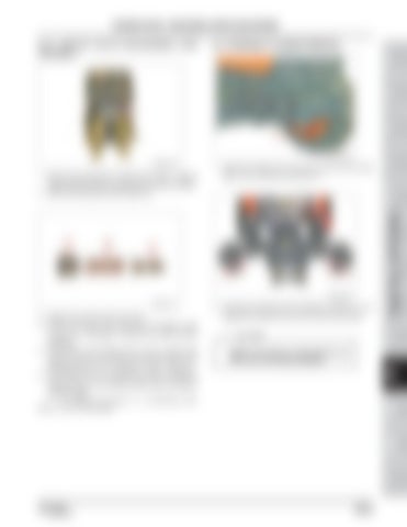
6.2 STEERING CYLINDER REMOVAL
R69WA32A
TRANSMISSION TRANSMI SSION R69WA33A
FRONT BRAKE AXLE
3. Install in the reverse order of removal. 4. Check the O-ring on the outer plug, and replace it with a new one if damaged. Grease the surface before installation. 5. If the control screw setting does not work, measure the pressure and turn the screw to set the pressure to the specified pressure 110~115 Kgf/cm² (1,564 ~ 1,635 psi). 6. The pressure can be measured by disconnecting the hydraulic hose on the steering cylinder side, and fitting a pressure gauge.
2. Unscrew the ball joint end mounting nut (RH/LH) (1) to separate the ball joint end (2) from the front axle case.
CAUTION •
Replace the split pin of the ball joint end with a new one during installation.
FRONT STEERING AXLE SYSTEM
R69WA31A
REAR BRAKE AXLE
REAR HSTAXLE
TRANSMI HST
1. Remove the outer plug (1) using a hex wrench. Mark its original position before unscrewing it for pressure setting. 2. Remove the spring (2) and the spool (3).
1. Install the safety jack to the front axle and front axle frame. Then, remove one front tire (1).
Dealer Copy -- Not forSSION Resale
R69WA30A
CLUTCH
ENGINE
GENERAL
6.1.3. RELIEF VALVE DISASSEMBLY AND ASSEMBLY
A/C AND INDEX HEATER
HYDRAULIC ELECTRIC & DIAGNOSIS SYSTEM
HYDRAULIC STEERING SYSTEM
Or, refer to the section "4.1 STEERING UNIT RELIEF VALVE PRESSURE".
DR72-W00
283 of 450
10-25


