Bobcat CT2035 2000 Series Compact Tractor Service Manual 7398896 (12-19)

Page 264

CLUTCH

ENGINE

1

TRANSMI SSION HST

TRANSMI SSION TRANSMISSION

2

3

REAR HSTAXLE

4 5 A

6

REAR BRAKE AXLE

7 B

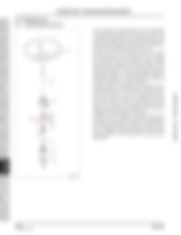
The turning force of the steering wheel (1) is transmitted through the handle shaft (2) to the handle shaft which is connected to the spline of the steering spool (7). The spool (7) is installed in the sleeve (4) which is installed in the steering unit housing (3). The spool (7) and sleeve (4) are fixed by the centering spring (6) and pin (5). The pin hole (A) on the sleeve (4) is fit to the outer diameter of the pin (5), but the pin hole (B) on the spool (7) is larger than the outer diameter of the pin, holding the pin loosely. Therefore, the spool (7) rotates with the steering connecting shaft (2) simultaneously, but the sleeve rotates approx. 10° later than the spool. When the spool stops rotating, the sleeve stops after rotating the remainder of approx. 10°. This is because the spool and sleeve are fixed by the centering spring (6). In other words, when the spool (7) and sleeve (4) are rotating clockwise or counterclockwise, being away from each other for approx. 10°, the oil hole for the left turn or the oil hole for the right turn is aligned to form the oil passage. When the spool (7) stops rotating and the sleeve (4) is returned to its original position (position relative to the spool) by the centering spring (6), the oil passage for the neutral position is formed. One end of the drive shaft (8) is connected to the pin (5) through the spool (7) while its other end is connected to the Gerotor in the Gerotor pump (9). The Gerotor pump (9) is operated whenever the steering wheel is turned, and it is installed to the steering system to make manual steering possible in case of engine shut-off or gear pump malfunction.

FRONT BRAKE AXLE

8

9

STEERING SYSTEM FRONT AXLE

10

A/C AND INDEX HEATER

HYDRAULIC ELECTRIC & DIAGNOSIS SYSTEM

HYDRAULIC STEERING SYSTEM

R52W903A

10-6264 of 450

DR72-W00

Dealer Copy -- Not for Resale

2.2 STEERING UNIT 2.1.1. OPERATING PRINCIPLE

GENERAL

SAFETY FIRST

STEERING SYSTEM - STRUCTURE AND OPERATING PRINCIPLE


Turn static files into dynamic content formats.

Create a flipbook

Articles inside

ELECTRIC SYSTEM AND DIAGNOSIS -

1min
pages 434-436

ELECTRIC SYSTEM AND DIAGNOSIS - ELECTRIC COMPONENTS

9min
pages 374-396

HYDRAULIC SYSTEM - DISASSEMBLY, SERVICE AND ASSEMBLY

1min
pages 332-337

HYDRAULIC SYSTEM - DISASSEMBLY, SERVICE AND ASSEMBLY

1min
pages 329-331

HYDRAULIC SYSTEM - DISASSEMBLY, SERVICE AND ASSEMBLY

2min
pages 324-328

HYDRAULIC SYSTEM - STRUCTURE AND OPERATING PRINCIPLE

4min
pages 301-306

HYDRAULIC SYSTEM - STRUCTURE AND OPERATING PRINCIPLE

5min
pages 294-300

HYDRAULIC SYSTEM - STRUCTURE AND OPERATING PRINCIPLE

2min
pages 292-293

STEERING SYSTEM - DISASSEMBLY, SERVICE AND ASSEMBLY

1min
pages 284-285, 287-291

STEERING SYSTEM - DISASSEMBLY, SERVICE AND ASSEMBLY

1min
page 283

STEERING SYSTEM - DISASSEMBLY, SERVICE AND ASSEMBLY

1min
page 281

STEERING SYSTEM - DISASSEMBLY, SERVICE AND ASSEMBLY

1min
page 280

STEERING SYSTEM - DISASSEMBLY, SERVICE AND ASSEMBLY

1min
pages 277-278

STEERING SYSTEM - STRUCTURE AND OPERATING PRINCIPLE

3min
pages 267-271

STEERING SYSTEM - STRUCTURE AND OPERATING PRINCIPLE

2min
pages 264-266

MEMO

1min
pages 258-259, 261-263

FRONT AXLE - DISASSEMBLY, SERVICE AND ASSEMBLY

1min
pages 256-257

FRONT AXLE - DISASSEMBLY, SERVICE AND ASSEMBLY

2min
pages 252-255

FRONT AXLE - MEASUREMENT AND ADJUSTMENT 4.8 TOOTH CONTACT FOR UPPER BEVEL GEARS AND FINAL DRIVE BEVEL GEARS

4min
pages 238-251

FRONT AXLE - MEASUREMENT AND ADJUSTMENT

1min
page 237

FRONT AXLE - MEASUREMENT AND ADJUSTMENT

2min
pages 235-237

FRONT AXLE - OPERATING PRINCIPLE

1min
pages 230-231

MEMO

1min
pages 224, 226-228

REAR AXLE - DISASSEMBLY, SERVICING AND ASSEMBLY

1min
pages 210, 212-213

REAR AXLE - DISASSEMBLY, SERVICING AND ASSEMBLY

1min
page 209

REAR AXLE - DISASSEMBLY, SERVICING AND ASSEMBLY

1min
pages 208-209

REAR AXLE - DISASSEMBLY, SERVICING AND ASSEMBLY

1min
page 206

REAR AXLE - DISASSEMBLY, SERVICING AND ASSEMBLY

1min
page 205

REAR AXLE - DISASSEMBLY, SERVICING AND ASSEMBLY

1min
page 204

REAR AXLE - DISASSEMBLY, SERVICING AND ASSEMBLY

1min
page 203

REAR AXLE - DISASSEMBLY, SERVICING AND ASSEMBLY

1min
page 202

REAR AXLE - TROUBLESHOOTING 3. TROUBLESHOOTING

2min
pages 192-194

2. OPERATING PRINCIPLE

1min
pages 190-191

HST - MEASUREMENT AND ADJUSTMENT

4min
pages 172-185

3. TROUBLESHOOTING

2min
pages 170-171

TRANSMISSION - DISASSEMBLY, SERVICE AND ASSEMBLY

6min
pages 156, 158-169

TRANSMISSION - DISASSEMBLY, SERVICE AND ASSEMBLY

1min
pages 154-155

TRANSMISSION - DISASSEMBLY, SERVICE AND ASSEMBLY

1min
pages 150-153

TRANSMISSION - SPECIFICATIONS

4min
pages 129-135

ENGINE - ENGINE DISASSEMBLY AND SERVICING

5min
pages 118-126

ENGINE - ENGINE DISASSEMBLY AND SERVICING

6min
pages 110-117

ENGINE - MEASUREMENT AND ADJUSTMENT 5. MEASUREMENT AND ADJUSTMENT

3min
pages 72-75

ENGINE - OPERATING PRINCIPLE

9min
pages 60-69

ENGINE - OPERATING PRINCIPLE

6min
pages 51-60

ENGINE - SPECIFICATIONS

1min
page 50

ENGINE - ENGINE IDENTIFICATION

1min
pages 44-45

SAFETY FIRST - SAFETY TIPS

1min
pages 13-14

SAFETY FIRST - SAFETY TIPS

2min
pages 10-12

FORWARD

1min
page 4

FORWARD

1min
pages 3-4
Issuu converts static files into: digital portfolios, online yearbooks, online catalogs, digital photo albums and more. Sign up and create your flipbook.
Bobcat CT2035 2000 Series Compact Tractor Service Manual 7398896 (12-19) by www.heydownloads.com - Issuu