4.6 BACKLASH FOR SPIRAL BEVEL PINION AND 23 SPIRAL BEVEL GEAR
CLUTCH
ENGINE
GENERAL
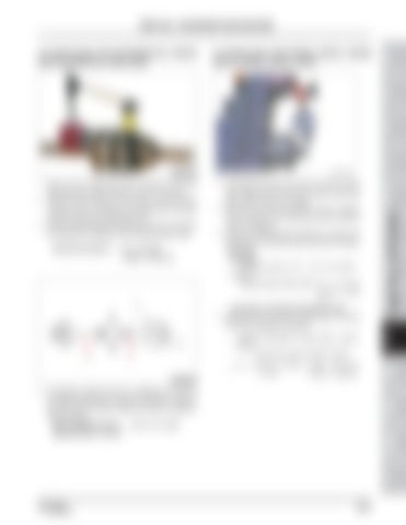
4.5 BACKLASH FOR DIFFERENTIAL PINION AND DIFFERENTIAL SIDE GEAR
SAFETY FIRST
FRONT AXLE - MEASUREMENT AND ADJUSTMENT
Standard backlash for gear teeth x spline = radius Center line radius of teeth contact =
0.1 ~ 0.3 mm x 12 mm 0.07 ~ 0.21 mm = 17 mm (0.003 ~ 0.008 in)
T46W814A
TRANSMISSION TRANSMI SSION TRANSMI HST REAR HSTAXLE
A/C AND INDEX HEATER
HYDRAULIC ELECTRIC & DIAGNOSIS SYSTEM
HYDRAULIC STEERING SYSTEM
4. If necessary, replace the shim (1) installed on the back of the differential side gear to adjust the backlash. However, the shims with the same thickness should be installed in both side gears. Size of adjusting shim: . .... 0.8, 1.0, 1.2 mm (Standard shim: 1.0 mm)
REAR BRAKE AXLE
• Calculation of standard backlash for spline
4. Adjust the shim (2) if the 21 bevel gear (1) should be moved to adjust the backlash.
Dealer Copy -- Not forSSION Resale
Standard backlash:....... 0.1 ~ 0.3 mm (0.004 ~ 0.012 in)
1. Assemble the spiral bevel pinion shaft, 21 bevel gear, differential case and axle support differential gear shaft as shown in the figure. 2. Set the lever type dial indicator so that it contacts with the spline of the spiral bevel pinion shaft as shown in the figure. 3. With both differential gear shaft fixed, measure the backlash by moving the spiral bevel pinion shaft by hand lightly. • Backlash Standard spline: 0.07 ~ 0.21 mm (0.003 ~ 0.008 in) Standard gear teeth radius: 0 .1 ~ 0.3 mm (0.004 ~ 0.012 in)
FRONT BRAKE AXLE
1. Set the front differential case assembly with both differential gear shafts inserted as shown in the figure. 2. Install the dial indicator (lever type) so that its pointer contacts with the surface of the differential side gear through the hole of the differential case. 3. Hold one differential gear shaft with a hand and measure the backlash by rotating the other differential gear shaft.
R69W928A
FRONT STEERING AXLE SYSTEM
T46W813A
DR72-W00
235 of 450
9-11


