OPERATIONAL PERFORMANCE TEST / Engine 2. When measurement is started from cylinder No.1, perform the same measurement to all
cylinder No.4, perform the same measurement to all valves indicated with
valves indicated with mark ● in the following table after measuring cylinder No.1. (When measurement is started from
mark ○ in the following table after measuring cylinder No.4.)
No.1
Cylinder No. Valve Location When measurement is started from cylinder No.1 When measurement is started from cylinder No.4
No.2
I
E
I
●
●
●
No.3 E
I
No.4 E
I
E
○
○
● ○
○
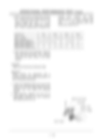
3. After rotating the crank shaft 360 ?, align the TDC mark with the pointer. Then, continue measuring the other valves in the same manner. Evaluation: Refer to the Performance Standard Table Adjustment: Please perform the adjustment with a procedure similar to the measuring method, if it has not standard dimensions. 1. Loosen the adjusting screw lock nuts for the rocker arms. Insert the feeler gauge set of the standard size, and adjust the adjusting screws. 2. After adjusting, retighten the lock nut to specification. Recheck the valve clearance after tightening the lock nut.
#FLWUVKPI 5ETGY .QEM 0WV 4QEMGT #TO (GGNGT )CWIG
8CNXG 5VGO
4 ‑155
