Mustang Articulated Loader AL 406 AL 506 Service Manual(50940008) - PDF DOWNLOAD

Page 28

Maintenance — Air Cleaner Air Cleaner

3. Clean any debris from the housing. Leave the inner filter element installed during this step to prevent debris from entering the engine intake manifold.

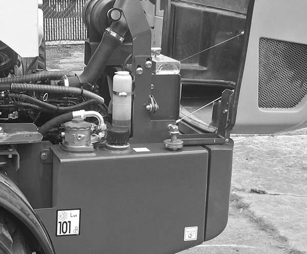
IMPORTANT: Do not operate the engine without the air cleaner components installed or damage to the engine could occur. Failure to follow air cleaner servicing instructions can also cause engine damage. The air cleaner consists of an outer (primary) filter element, an inner (secondary) filter element, an air filter restriction indicator and a dust valve. If the air cleaner becomes restricted, the air filter restriction indicator (1, Figure 5) turns red to warn the operator that the element(s) require service. Push the reset button located on the end of the indicator after installing a clean filter element(s). Pinching the dust valve (2, Figure 5) opens a slit at the end of the valve, allowing accumulated dust in the end of the element cover to drop out without removing the cover.

1

Only replace the inner element every third time the outer element is replaced, unless the outer element is damaged or the inner element is dirty.

4

3

2

Be sure that the restriction indicator, air cleaner intake hose, clamps and mounting bracket hardware are properly tightened.

6

Accessing the Outer and Inner Filter Elements 1. Perform the “Mandatory Procedure” on page 4.

Safety

5

Shutdown

2. Open the engine cover.

7

3. Unlatch the clamps on the air cleaner housing and remove the element cover. 4. Clean any debris from the cover.

Changing the Outer Filter Element 1. Perform the “Mandatory Procedure” on page 4.

Safety

Figure 5 – Dual-Element Air Cleaner Shutdown

1. Air Filter Restriction Indicator 2. Dust Valve 3. Element Cover 4. Clamp 5. Air Cleaner Housing 6. Outer Filter Element 7. Inner Filter Element

2. Carefully remove the outer filter element. Do not remove the inner filter element unless it is to be replaced. See “Changing the Inner Filter Element” on page 23. NOTE: Cleaning the outer filter element is not recommended; replace instead.

50940008/AP0311

4. Install the new outer filter element.

22

PRINTED IN U.S.A.


Turn static files into dynamic content formats.

Create a flipbook

Articles inside

Troubleshooting — Hydrostatic Drive System

1min
page 208

Troubleshooting — Hydraulic System

1min
page 206

Troubleshooting — Engine

1min
page 203

Battery Installation

2min
pages 190-201

Drive Control System— Pedal Calibration Procedure

1min
pages 188-189

Drive Control System— Pedal Calibration Procedure

1min
page 187

Drive Control System—

2min
pages 185-186

Drive Control System— Electrical Status Error Reporting Screen

1min
page 183

Drive Control System— Electrical Inputs/Outputs Monitoring Screen

1min
page 182

Drive Control System— Software Log Monitoring Screen

1min
page 181

Drive Control System— Plus+1 Service Tool Navigation/Overview

1min
page 180

Drive Control System—

1min
page 179

Drive Control System— Drive

1min
page 178

Drive Control System— Machine Controller

1min
page 177

Drive Control System— Machine Controller

1min
pages 176-177

Drive Control System— Machine Controller

1min
page 175

Drive Control System—

1min
page 173

Hydraulics — Raising Machine for Drive System Troubleshooting

1min
page 167

Hydraulics — Hydraulic Cylinder Disassembly/Assembly

1min
page 147

Hydraulics — Tilt Cylinder Removal

1min
pages 144-145

Hydraulics — Lift/Tilt Lock, Power-A-Tach® System and Auxiliary

1min
page 141

Hydraulics — 2-Spool Control Valve Removal

1min
pages 132-133

Hydraulics — Steering Circuit Pressure Test

1min
page 131

Hydraulics — Work System Pressure Tests

1min
page 130

Hydraulics — Drive System Pressure Tests

1min
page 129

Hydraulics — Drive System Pressure Tests

1min
page 128

Hydraulics — Hydraulics Troubleshooting Diagnostic Flow Charts

1min
page 120

Hydraulics — Hydraulics Troubleshooting Diagnostic Flow Charts

1min
page 114

Hydraulics — Hydrostatic Drive System

1min
page 112

Hydraulics — Work Hydraulics Troubleshooting

1min
page 111

Hydraulics — Work Hydraulics Troubleshooting

1min
page 110

Hydraulics — Work Hydraulics Troubleshooting

1min
page 109

Engine — Drive Coupling Removal

1min
page 93

Chassis — Lift Arm Installation

1min
pages 82-83

Chassis — Lift Arm Installation

1min
page 81

Operation — Lift/Tilt Lock

1min
page 66

Operation — Hand Throttle

1min
page 65

Operation — Steering Column

1min
pages 64-65

Operation — Warning Indicators

1min
pages 62-63

Operation — Cab Controls (Cab only)

1min
page 60

Operation — Instrument Panel and Indicators

1min
page 58

Operation — Controls and Switches

1min
page 57

Operation — Operation Safety

1min
page 55

Maintenance — Storing the Loader

1min
page 50

Maintenance — Electrical System

4min
pages 47-49

Maintenance — Electrical System

1min
pages 46-47

Maintenance — Wheels and Tires

1min
page 39

Maintenance — Brake Fluid Reservoir

1min
pages 38-39

Maintenance — Planetary Axles

1min
page 37

Maintenance — Planetary Axles

1min
pages 36-37

Maintenance — Hydraulic System Maintenance

1min
page 35

Maintenance — Air Conditioning Maintenance

1min
page 34

Maintenance — Fuel System

1min
pages 32-33

Maintenance — Engine Cooling System

2min
pages 30-31

Maintenance — Engine Cooling System

1min
page 29

Maintenance — Air Cleaner

1min
page 28

Maintenance — Engine Maintenance

1min
page 27

Table of Contents

18min
pages 6-15, 17, 20-23
Issuu converts static files into: digital portfolios, online yearbooks, online catalogs, digital photo albums and more. Sign up and create your flipbook.
Mustang Articulated Loader AL 406 AL 506 Service Manual(50940008) - PDF DOWNLOAD by www.heydownloads.com - Issuu