1 minute read
Operation — Lift/Tilt Lock


Lift/Tilt Lock
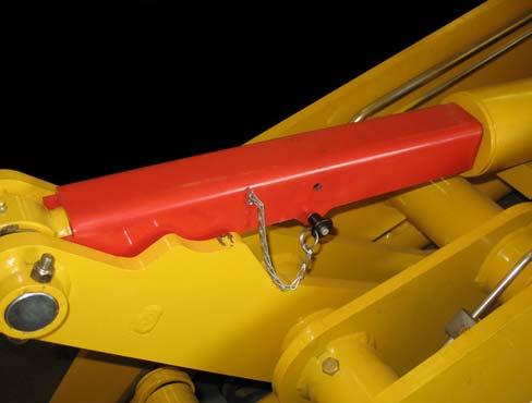
AL 400 Series Machines
1.Remove the spring pins (1, Figure 14), and remove the lock bar (2) from the machine.
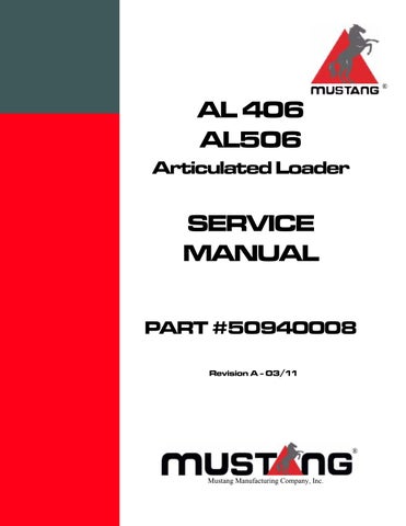
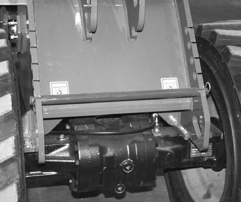
AL 500 Series Machines
1.Remove the quick-release pin (1, Figure 15), and lift the cylinder stop channel (2) off the machine.
2.Tilt the attachment/hitch as required to align holes in tilt bracket (3) with holes in lift arms (4). Slide the lock bar (2) all the way through the locking holes (3) in the lift arm, the tilt cylinder linkage and the front frame.
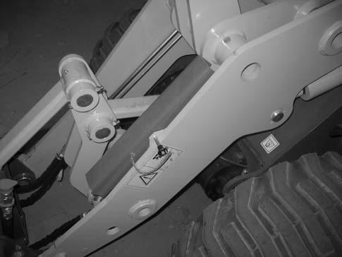
3.Replace the spring pins (1) into the ends of the lock bar.
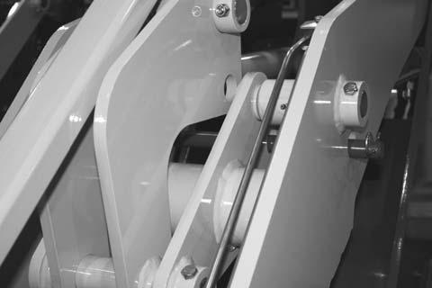
2.Tilt the attachment/hitch back as required and place the cylinder stop channel (2) under tilt indicator (1) and over the tilt cylinder to brace the tilt cylinder in the extended position.
3.Replace the quick-release (1) into the cylinder stop channel so it passes under the tilt cylinder rod.