1 minute read
Hydraulics — Lift/Tilt Lock, Power-A-Tach® System and Auxiliary
STEP 11
Lower the platform. See “Lowering the Platform” on page62.
STEP 12
Start the engine and bleed the air out of the hydraulic control valve by cycling through the joystick function three times.
Check the hydraulic reservoir fluid level and fill as needed. Refer to See “Fluid Capacities/Lubricants” on page11.
STEP 13
Start the machine and bleed the air out of the hydraulic control valve by cycling through the joystick function three times.
Lift/Tilt Lock, Power-A-Tach® System and Auxiliary Hydraulics Valve Locations
400 Series 41250 and Up 500 Series 51242 and Up
Lift/Tilt Lock Valves
The lift and tilt lock valves lock-out the lift arm lift and tilt functions whenever the operator seat is not occupied. Malfunctioning lift and/or tilt lock valves can result in inoperative lift and/or tilt functions.
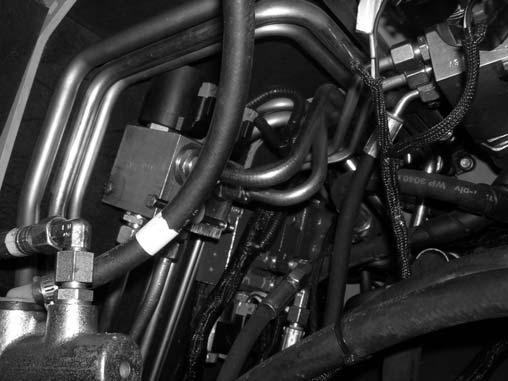
The tilt (23) and lift (21) lock valves are fastened to the underside of the operator’s platform, under the operator’s seat, next to the Power-A-Tach ® system hydraulic valve (22) and auxiliary hydraulic valve (20).
Power-A-Tach® System Hydraulic Valve
The Power-A-Tach ® system valve (22) contols the Power-A-Tach ® system cylinder, if equipped to lock attachments into the attachment plate.
The Power-A-Tach ® system valve (22) is fastened to the underside of the operator’s platform, under the operator’s seat between the locking valves (21 & 23) and the auxiliary hydraulic valve (20).
Auxiliary Hydraulic Valve
The auxiliary hydraulic valve diverts hydraulic flow into the auxiliary hydraulics circuit.
The auxiliary hydraulic valv e (20) is fastened to the underside of the operator’s platform, under the operator’s seat next to the lift and tilt lock valves (20 & 21) and the Power-A-Tach® hydraulic valve (22).


