2 minute read
Drive Control System—


Drive Controller Pedal Calibration Parameters
Drive Controller Pedal Calibration Parameters
Poor or no control response will result if the pedals are out of calibration.The PLUS+1 module must be recalibrated whenever:
•The articulated loader speed control or brake/inch pedal mechanical components are removed for service or replacement.
•The electronic pedal sensor is removed for service or replacement.
•The PLUS+1 module is replaced.
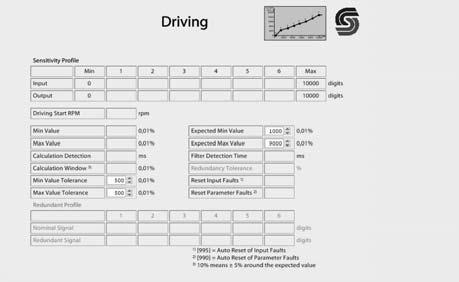
Driving Pedal Parameter Screen
The “Driving” screen is used to change minimum and maximum values used in pedal calibration.
NOTE: Minimum/maximum pedal calibration values needs to be changed only if pedal calibration is not possible because actual pedal travel falls outside the indicated minimum and maximum position values. Values on this screen are expressed in digits instead of volts.
Actual pedal position can be determined in real-time using the pedal position input field on the “Electrical Inputs/Outputs” monitoring screen (item 3, page176).
To convert pedal mV values to digits, multiply mV by 2 (example: 500 mV X 2 = 1000 digits.
To access the “Driving” screen, select “Diagnostic Navigator”: “Parameter Functions > Inputs > Driving.”
NOTE: Adjust this value only in increments of 100 and then test. Extreme changes to this value will reduce the effective control range of the drive pedal.
2.This field indicates the maximum expected drive pedal fully depressed or full travel position.
NOTE: Adjust this value only in increments of 100 and then test. Extreme changes to this value will reduce the effective control range of the drive pedal.
3.These fields indicate the tolerance modifiers for the expected minimum and maximum values (1 and 2). Numbers in these fields set a range above and below minimum and maximum values (1 and 2) that will be accepted during the calibration process.
NOTE: Adjust these values only in increments of 10, and then test. Extreme changes to this value will reduce the effective control range of the drive pedal.
NOTE: Changes made in this screen do not take effect until the download button is clicked. This button is located near the top of the screen.
Pump Profiling Screen/Drive “Creep” Adjustment
The “Pump Profiling Automotive” screens are used to adjust machine “creep”.
“Creep” occurs when the machine moves if the drive is shifted to forward or reverse while engine speed is below 1200 RPM.
There are two “Pump Profiling Automotive” screens: one for low- (Mode 4), and one for high-speed (Mode 2) travel modes.
To access the “Pump Profiling Automotive” screens:
•For high-speed, select “Diagnostic Navigator”: “Parameter Functions > Pump > Mode 2 Profiling Automotive.”
1.This field indicates the minimum expected drive pedal neutral position.
•For low-speed, select “Diagnostic Navigator”: “Parameter Functions > Pump > Mode 4 Profiling Automotive.”
Values in fields (1 and 2) determine output to the drive pump based on pedal input and engine speed.
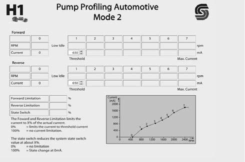
1.This field indicates the pump profiling threshold in the forward drive direction. Lowering the value in this field will prevent creep; increasing the value will increase creep speed.
NOTE: Adjust this value only in increments of 10 and then test. Extreme changes to this value can disable the drive or cause immediate, aggressive uncontrolled drive activation.
2.This field indicates the pump profiling threshold in the reverse drive direction. Lowering the value in this field will prevent creep; increasing the value will increase creep speed.
NOTE: Adjust this value only in increments of 10 and then test. Extreme changes to this value can disable the drive or cause immediate, aggressive uncontrolled drive activation.
NOTE: Changes made in this screen do not take effect until the download button is clicked. This button is located near the top of the screen.