2 minute read
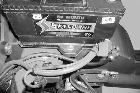
Battery Installation


STEP 1
Warning
Sparks or flame can cause hydrogen gas in a battery to explode. To prevent an explosion, do the following:
When you disconnect the battery cables, always disconnect the negative (-) battery cable first.
When you connect the battery cables, always connect the negative (-) battery cable last.
Do not short circuit the battery posts with metal items.
Do not weld, grind or smoke near a battery.
Install
STEP 2
Install
STEP 3
Install the negative (3) and positive (4) battery cables.
STEP 4
Lower the platform. See “Lowering the Platform” on page62.
Electrical Schematics — AL 400 Series (Serial Numbers 41250 and up) Complete Electrical Schematic
AL 400 Series (Serial Numbers 41250 and up) Complete Electrical Schematic
NOTE: AL400 and AL500 Series machines use the same wiring harnesses and schematics, but not all features are available on AL400 Series machines.
Electrical Schematics — AL 400 Series (Serial Numbers 41250 and up) Steering Column Electrical Schematic
AL 400 Series (Serial Numbers 41250 and up) Steering Column Electrical Schematic
NOTE: AL400 and AL500 Series machines use the same wiring harnesses and schematics, but not all features are available on AL400 Series machines.
Electrical Schematics — AL 400 Series (Serial Numbers 41250 and up) Chassis Electrical Schematic
AL 400 Series (Serial Numbers 41250 and up) Chassis Electrical Schematic
NOTE: AL400 and AL500 Series machines use the same wiring harnesses and schematics, but not all features are available on AL400 Series machines.
Electrical Schematics — AL 400 Series (Serial Numbers 41250 and up) Engine Electrical Schematic
AL 400 Series (Serial Numbers 41250 and up) Engine Electrical Schematic
NOTE: AL400 and AL500 Series machines use the same wiring harnesses and schematics, but not all features are available on AL400 Series machines.
Electrical Schematics — AL 400 Series (Serial Numbers 41250 and up) FOPS, Power-A-Tach® and Tail Light Electrical Schematic
AL 400 Series (Serial Numbers 41250 and up) FOPS, Power-A-Tach® and Tail Light Electrical Schematic
NOTE: AL400 and AL500 Series machines use the same wiring harnesses and schematics, but not all features are available on AL400 Series machines.
Electrical Schematics — AL 500 Series (Serial Numbers 51242 and up) Complete Electrical Schematic (Includes Air Conditioning Option)
AL 500 Series (Serial Numbers 51242 and up) Complete Electrical Schematic (Includes Air Conditioning Option)
Electrical Schematics — AL 500 Series (Serial Numbers 51242 and up) Steering Column Electrical Schematic (Includes Air Conditioning Option)
AL 500 Series (Serial Numbers 51242 and up) Steering Column Electrical Schematic (Includes Air Conditioning Option)
Electrical Schematics — AL 500 Series (Serial Numbers 51242 and up) Chassis Electrical Schematic (Includes Air Conditioning Option)
AL 500 Series (Serial Numbers 51242 and up) Chassis Electrical Schematic (Includes Air Conditioning Option)
Electrical Schematics — AL 500 Series (Serial Numbers 51242 and up) Engine Electrical Schematic (Includes Air Conditioning Option)
AL 500 Series (Serial Numbers 51242 and up) Engine Electrical Schematic (Includes Air Conditioning Option)
Electrical Schematics — AL 500 Series (Serial Numbers 51242 and up) FOPS, CAB, Power-A-Tach® and Tail Light Electrical Schematic (Includes Air Conditioning
AL 500 Series (Serial Numbers 51242 and up) FOPS, CAB, Power-A-Tach® and Tail Light Electrical Schematic (Includes Air Conditioning Option)
Electrical Schematics — AL 400 Series (Serial Numbers 41249 and below), AL 500 Series (Serial Numbers 51241 and below) Complete Electrical Schematic
AL 400 Series (Serial Numbers 41249 and below), AL 500 Series (Serial Numbers 51241 and below) Complete Electrical Schematic
50940008/AP0311