Drive Control System— Pedal Calibration Procedure Pedal Calibration Procedure
•
Perform this procedure if the status of either the brake/ inch, or speed control pedals is shown to be out of calibration in the Pedal Data window. See “Pedal Calibration Data” on page 182.
To calibrate the brake/inch pedal: “Diagnostic Navigator”: “Parameter Functions > Inputs > Inching > Setup Status.”
IMPORTANT: If pedal mechanical components, the electronic pedal sensor and/or the PLUS+1 module is replaced, calibration must be forced because the pedals may be out-of-calibration, even though they will register as being in-calibration. See “Forcing Pedal Parameter Calibration” on page 182. If calibrating the brake/inch pedal: 1. Tilt the operator platform up as directed in the operator’s manual and lock the platform in the tilted position using the platform tilt support.
4. Press the pedal down all the way. The top status flag changes to yellow and displays a “Calibr. started” message. The “Max Value” field displays a numeric value for the depressed pedal calibration point.
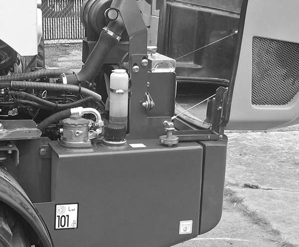
2. Remove spring clip (Z) from push rod (X). Remove push rod (X) from the brake valve.
Z
X
5. Release the pedal, and if necessary, pull the pedal back until it reaches its maximum released travel point. The top status flag changes to green and displays a “All points calibr.” message, and the bottom status flag also changes to green and displays a “Calibration complete” message. The “Min Value” field displays a numeric value for the released pedal calibration point.
Brake Valve with Push Rod Removed
3. Access the Setup Status window by clicking on the following links: •
To calibrate the speed control pedal: “Diagnostic Navigator”: “Parameter Functions > Inputs > Driving > Setup Status.”
6. If calibrating the brake/inch pedal. a. Replace the push rod back into the brake valve. Connect the push rod to the brake pedal with the spring clip. b. Tilt the operator platform down.
PRINTED IN U.S.A.
181
50940008/AP0311