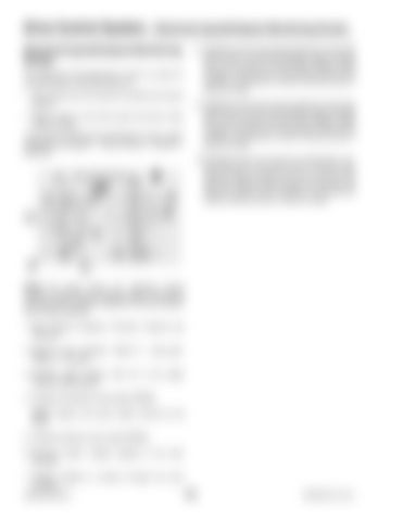
Drive Control System— Electrical Inputs/Outputs Monitoring Screen Electrical Inputs/Outputs Monitoring Screen The “Electrical Inputs/Outputs” screen is useful for troubleshooting. It provides access to: • Input values from the machine controller and various sensors. • Output values to the drive pump and drive motor solenoid valves. To access the “Electrical Inputs/Outputs” screen, select “Diagnostic Navigator”: “Log Functions > System > Electrical.”
1
9. Feedback loop for the reverse solenoid on the drive/ piston pump. The left value displays signal strength sent to the solenoid; the right value displays signal strength returned from the solenoid. Good circuit condition is indicated by closely matching values in these two fields. 10.Feedback loop for the pressure compensation override solenoid on the drive motor. The left value displays signal strength sent to the solenoid; the right value displays signal strength returned from the solenoid. Good circuit condition is indicated by closely matching values in these two fields.
8 2
8. Feedback loop for the forward solenoid on the drive/ piston pump. The left field displays signal strength sent to the solenoid; the right fields displays signal strength returned from the solenoid. Good circuit condition is indicated by closely matching values in these two fields.
9 10
3 4 5 6
7
NOTE: The figure shows the “Electrical Inputs/ Outputs” screen with the machine engine running and the forward drive direction selected in the drive system with low gear selected. 1. Drive direction indication; “Forward”, “Neutral” and “Reverse”. 2. High/Low gear indication; “Mode 2” = high gear; “Mode 4” = low gear. 3. Indicates pedal position; 500 mV is the target “Neutral” pedal position. 4. Indicates drive/piston pump speed (RPMs). NOTE: Engine and pump speed should be the same. 5. Indicates hydraulic motor speed (RPMs). 6. Electrical system voltage supplied to the drive controller. 7. Voltage supplied to sensors through the drive controller. 50940008/AP0311
176
PRINTED IN U.S.A.


