Mustang Articulated Loader AL 406 AL 506 Service Manual(50940008) - PDF DOWNLOAD

Page 177

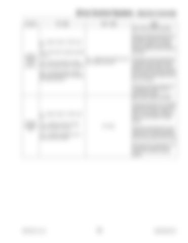
Drive Control System— Machine Controller Function

“IN” LEDs

“OUT” LEDs

Notes Later serial number machines

(1) -- Ignition switch in "RUN" position (24) -- Seat switch indicates operator Auxiliary in seat Hydraulics (21) -- Signal sent to Reverse auxilFlow (23) -- Reverse direction auxiliary iary hydraulics solenoid (Reverse) hydraulics joystick button is pressed (25) -- Forward direction auxiliary hydraulics joystick button is pressed (for continuous flow)

Reverse auxiliary hydraulics flow is activated if the ignition switch is in the “RUN” position, the operator seat is occupied and the reverse direction auxiliary hydraulics joystick is pressed Continuous reverse hydraulics flow is activated if the forward direction hydraulics joystick button is then pressed, and both buttons are held for two seconds. Reverse hydraulics flow will then continue after the buttons are released Continuous reverse hydraulics flow is deactivated if either button is momentarily pressed Early serial number machines Auxiliary hydraulics flow is activated if the ignition switch is in the “RUN” position, the operator’s platform is down and the auxiliary hydraulics lever is in the forward or reverse position

(1) -- Ignition switch in "RUN" position Auxiliary (12) -- ROPS tilt switch indicates Hydraulics operator platform is down Flow

No Output

(14) -- Auxiliary hydraulics lever in forward/reverse position

Continuous hydraulics flow is activated when the auxiliary hydraulics control lever is moved past the forward/reverse position into the detent Hydraulics flow is deactivated when the auxiliary hydraulics lever is moved to the neutral (centered) position

PRINTED IN U.S.A.

171

50940008/AP0311


Turn static files into dynamic content formats.

Create a flipbook

Articles inside

Troubleshooting — Hydrostatic Drive System

1min
page 208

Troubleshooting — Hydraulic System

1min
page 206

Troubleshooting — Engine

1min
page 203

Battery Installation

2min
pages 190-201

Drive Control System— Pedal Calibration Procedure

1min
pages 188-189

Drive Control System— Pedal Calibration Procedure

1min
page 187

Drive Control System—

2min
pages 185-186

Drive Control System— Electrical Status Error Reporting Screen

1min
page 183

Drive Control System— Electrical Inputs/Outputs Monitoring Screen

1min
page 182

Drive Control System— Software Log Monitoring Screen

1min
page 181

Drive Control System— Plus+1 Service Tool Navigation/Overview

1min
page 180

Drive Control System—

1min
page 179

Drive Control System— Drive

1min
page 178

Drive Control System— Machine Controller

1min
page 177

Drive Control System— Machine Controller

1min
pages 176-177

Drive Control System— Machine Controller

1min
page 175

Drive Control System—

1min
page 173

Hydraulics — Raising Machine for Drive System Troubleshooting

1min
page 167

Hydraulics — Hydraulic Cylinder Disassembly/Assembly

1min
page 147

Hydraulics — Tilt Cylinder Removal

1min
pages 144-145

Hydraulics — Lift/Tilt Lock, Power-A-Tach® System and Auxiliary

1min
page 141

Hydraulics — 2-Spool Control Valve Removal

1min
pages 132-133

Hydraulics — Steering Circuit Pressure Test

1min
page 131

Hydraulics — Work System Pressure Tests

1min
page 130

Hydraulics — Drive System Pressure Tests

1min
page 129

Hydraulics — Drive System Pressure Tests

1min
page 128

Hydraulics — Hydraulics Troubleshooting Diagnostic Flow Charts

1min
page 120

Hydraulics — Hydraulics Troubleshooting Diagnostic Flow Charts

1min
page 114

Hydraulics — Hydrostatic Drive System

1min
page 112

Hydraulics — Work Hydraulics Troubleshooting

1min
page 111

Hydraulics — Work Hydraulics Troubleshooting

1min
page 110

Hydraulics — Work Hydraulics Troubleshooting

1min
page 109

Engine — Drive Coupling Removal

1min
page 93

Chassis — Lift Arm Installation

1min
pages 82-83

Chassis — Lift Arm Installation

1min
page 81

Operation — Lift/Tilt Lock

1min
page 66

Operation — Hand Throttle

1min
page 65

Operation — Steering Column

1min
pages 64-65

Operation — Warning Indicators

1min
pages 62-63

Operation — Cab Controls (Cab only)

1min
page 60

Operation — Instrument Panel and Indicators

1min
page 58

Operation — Controls and Switches

1min
page 57

Operation — Operation Safety

1min
page 55

Maintenance — Storing the Loader

1min
page 50

Maintenance — Electrical System

4min
pages 47-49

Maintenance — Electrical System

1min
pages 46-47

Maintenance — Wheels and Tires

1min
page 39

Maintenance — Brake Fluid Reservoir

1min
pages 38-39

Maintenance — Planetary Axles

1min
page 37

Maintenance — Planetary Axles

1min
pages 36-37

Maintenance — Hydraulic System Maintenance

1min
page 35

Maintenance — Air Conditioning Maintenance

1min
page 34

Maintenance — Fuel System

1min
pages 32-33

Maintenance — Engine Cooling System

2min
pages 30-31

Maintenance — Engine Cooling System

1min
page 29

Maintenance — Air Cleaner

1min
page 28

Maintenance — Engine Maintenance

1min
page 27

Table of Contents

18min
pages 6-15, 17, 20-23
Issuu converts static files into: digital portfolios, online yearbooks, online catalogs, digital photo albums and more. Sign up and create your flipbook.
Mustang Articulated Loader AL 406 AL 506 Service Manual(50940008) - PDF DOWNLOAD by www.heydownloads.com - Issuu