Mustang Articulated Loader AL 406 AL 506 Service Manual(50940008) - PDF DOWNLOAD

Page 147

Hydraulics — Hydraulic Cylinder Disassembly/Assembly Hydraulic Cylinder Disassembly/ Assembly

Cylinder Disassembly

Except for some configuration differences, hydraulic cylinder disassembly, repair and assembly procedures will be mostly the same for all cylinders. Refer to the parts manual for specific part and part orientation information for specific cylinders. When backup rings are used with o-ring seals, always note the position of the backup ring (above or below the o-ring) when removing the seals for reassembly reference.

WARNING When disassembling hydraulic cylinders, NEVER use pneumatic or hydraulic pressure to aid in removing the piston and rod assembly from the cylinder barrel. Ignoring this warning may result in severe injury or death.

STEP 1

One-piece teflon piston seals can be difficult to install on the piston. Soaking the seals in hot 130°-140° F (54°-60° C), clean hydraulic oil for a short time prior to installation will make the seals more resilient and easier to install on the piston.

2

1

Before installing the piston and rod assembly into the barrel, lubricate the piston seals and wear rings liberally with clean hydraulic fluid. Using an engine piston ring compressor to compress the piston seals tightly for a short period of time will often aid in the assembly procedure.

3

G0908021

Refer to the following pages for the disassembly / assembly procedures: • “Cylinder Disassembly” on page 141. • “Cylinder Assembly” on page 145.

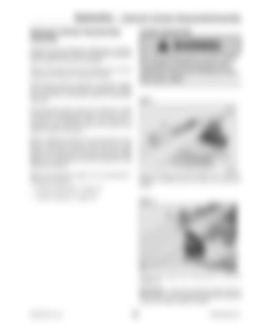
Clamp the base end of the cylinder (1) in a vice (2). Position a wooden block (3) under the cylinder as shown.

STEP 2 2

1

G0908023

Loosen and remove the head gland (1) from the cylinder (2). IMPORTANT: Protect the polished surface finish on the cylinder rod at all times by covering the polished surface with impact-resistant material. PRINTED IN U.S.A.

141

50940008/AP0311


Turn static files into dynamic content formats.

Create a flipbook

Articles inside

Troubleshooting — Hydrostatic Drive System

1min
page 208

Troubleshooting — Hydraulic System

1min
page 206

Troubleshooting — Engine

1min
page 203

Battery Installation

2min
pages 190-201

Drive Control System— Pedal Calibration Procedure

1min
pages 188-189

Drive Control System— Pedal Calibration Procedure

1min
page 187

Drive Control System—

2min
pages 185-186

Drive Control System— Electrical Status Error Reporting Screen

1min
page 183

Drive Control System— Electrical Inputs/Outputs Monitoring Screen

1min
page 182

Drive Control System— Software Log Monitoring Screen

1min
page 181

Drive Control System— Plus+1 Service Tool Navigation/Overview

1min
page 180

Drive Control System—

1min
page 179

Drive Control System— Drive

1min
page 178

Drive Control System— Machine Controller

1min
page 177

Drive Control System— Machine Controller

1min
pages 176-177

Drive Control System— Machine Controller

1min
page 175

Drive Control System—

1min
page 173

Hydraulics — Raising Machine for Drive System Troubleshooting

1min
page 167

Hydraulics — Hydraulic Cylinder Disassembly/Assembly

1min
page 147

Hydraulics — Tilt Cylinder Removal

1min
pages 144-145

Hydraulics — Lift/Tilt Lock, Power-A-Tach® System and Auxiliary

1min
page 141

Hydraulics — 2-Spool Control Valve Removal

1min
pages 132-133

Hydraulics — Steering Circuit Pressure Test

1min
page 131

Hydraulics — Work System Pressure Tests

1min
page 130

Hydraulics — Drive System Pressure Tests

1min
page 129

Hydraulics — Drive System Pressure Tests

1min
page 128

Hydraulics — Hydraulics Troubleshooting Diagnostic Flow Charts

1min
page 120

Hydraulics — Hydraulics Troubleshooting Diagnostic Flow Charts

1min
page 114

Hydraulics — Hydrostatic Drive System

1min
page 112

Hydraulics — Work Hydraulics Troubleshooting

1min
page 111

Hydraulics — Work Hydraulics Troubleshooting

1min
page 110

Hydraulics — Work Hydraulics Troubleshooting

1min
page 109

Engine — Drive Coupling Removal

1min
page 93

Chassis — Lift Arm Installation

1min
pages 82-83

Chassis — Lift Arm Installation

1min
page 81

Operation — Lift/Tilt Lock

1min
page 66

Operation — Hand Throttle

1min
page 65

Operation — Steering Column

1min
pages 64-65

Operation — Warning Indicators

1min
pages 62-63

Operation — Cab Controls (Cab only)

1min
page 60

Operation — Instrument Panel and Indicators

1min
page 58

Operation — Controls and Switches

1min
page 57

Operation — Operation Safety

1min
page 55

Maintenance — Storing the Loader

1min
page 50

Maintenance — Electrical System

4min
pages 47-49

Maintenance — Electrical System

1min
pages 46-47

Maintenance — Wheels and Tires

1min
page 39

Maintenance — Brake Fluid Reservoir

1min
pages 38-39

Maintenance — Planetary Axles

1min
page 37

Maintenance — Planetary Axles

1min
pages 36-37

Maintenance — Hydraulic System Maintenance

1min
page 35

Maintenance — Air Conditioning Maintenance

1min
page 34

Maintenance — Fuel System

1min
pages 32-33

Maintenance — Engine Cooling System

2min
pages 30-31

Maintenance — Engine Cooling System

1min
page 29

Maintenance — Air Cleaner

1min
page 28

Maintenance — Engine Maintenance

1min
page 27

Table of Contents

18min
pages 6-15, 17, 20-23
Issuu converts static files into: digital portfolios, online yearbooks, online catalogs, digital photo albums and more. Sign up and create your flipbook.
Mustang Articulated Loader AL 406 AL 506 Service Manual(50940008) - PDF DOWNLOAD by www.heydownloads.com - Issuu