Hydraulics — Hydraulics Troubleshooting Diagnostic Flow Charts Work Hydraulics Diagnostics (Continued) NOTE: The table below refers to the flow chart on the previous page. Item No.
1 2
Reference Information
Additional Information
See “Gear/Work Hydraulic Pump Removal” on page 149. See “Piston/Drive Hydraulic Pump Removal” on page 150.
Pump(s) have to be removed to access pump coupling components.
3
See “Hydraulic Piston/Drive Pump Diagnostics” on page 115.
Additional diagnostics specific to the pump(s) is required.
4
Refer to the parts manual for main relief valve parts information.
5
See “Operator Presence Diagnostics” on page 113.
Additional diagnostics specific to the operator presence control is required.
6
See “Drive Coupling Removal” on page 87.
Refer to the parts manual for drive coupling parts information.
7
See “Hydraulic Cylinder Disassembly/Assembly” on page 141.
General cylinder service information.
8
See “Steering Control Valve Removal” on page 156.
Refer to the parts manual for steering control valve parts information.
9
See “Steering Hydraulics Diagnostics” on page 109.
Work and steering hydraulics are integrated at points. Additional diagnostics may be required.
10
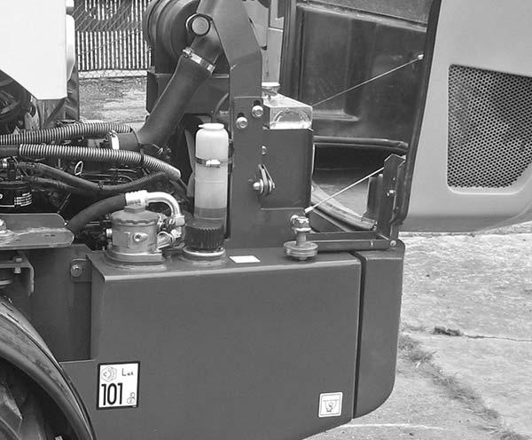
See “Work Pressure Test” on page 124 See: • “Fuse Locations” on page 37.
11 • “Engine Oil Level Check” on page 20. • “Drive Controller Error Codes” on page 172 and “Machine Controller Logic” on page 169.
50940008/AP0311
108
PRINTED IN U.S.A.