Template Name: OML_2_col Template Date: 1997_02_12
907871E
Alt= to hide template information Alt+ to display template information
844/642 Telehandler
ELECTRICAL
STEP 42
STEP 43
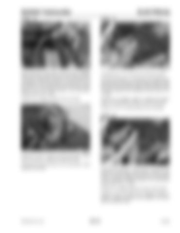
G0705116
Disconnect the crab steer wire harness (orange/ white and black wires) from the steer mode solenoid connector. Install the positive (+) test lead in the orange/white wire prong of the wire harness. With the key switch in the ON position and the steer mode switch in the crab steer position, the multimeter should read 12 to 13 volts. If there is no voltage proceed to the next step.
G0705113
Complete step 13 to remove the instrument panel. Connect the positive (+) test lead to the black/yellow wire terminal of the steer mode switch located on the left side of the instrument panel. With the key switch in the ON position the multimeter should read 12 to 13 volts. If there is no voltage, repair or replace the black/ yellow wire between the switch and the fuse panel. If there is 12 to 13 volts proceed to the next step.
STEP 44
G0705135
If there is 12 to 13 volts, but the crab steer mode does not function, replace the solenoid valve. Connect the wire harness to the crab-steer mode solenoid connector.
G0705112
Connect the positive (+) test lead to the green wire terminal of the steer mode switch. With the key switch in the ON position and the steer mode switch in the 4-WHEEL STEER position, the multimeter should read 12 to 13 volts. If there is no voltage replace the steer mode switch. If there is 12 to 13 volts, but no voltage in Step 41, repair or replace the green wire between the switch and the solenoid valve.
PRINTED IN U.S.A.
301-21
913250


