1 minute read
844/642 Telehandler HYDRAULICS


Step 41
Step 43
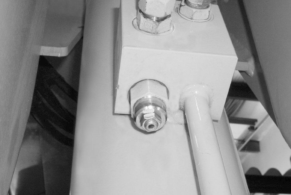
If a new counterbalance valve was installed, repeat Steps 40 and 42 to set the load check valve release pressure. Remove the pressure gauge from the cylinder and install the supply hose on the cylinder port.
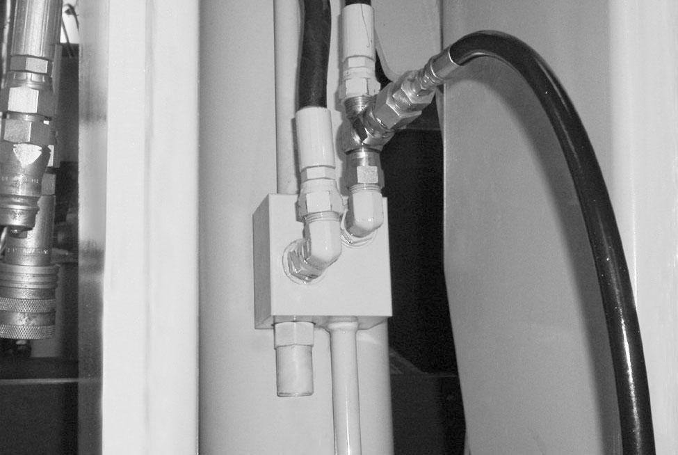
Remove the cover from the tilt cylinder load check valve.
NOTE: The cover is friction fit and can be loosened by twisting the cover on the valve cartridge.
Step 42
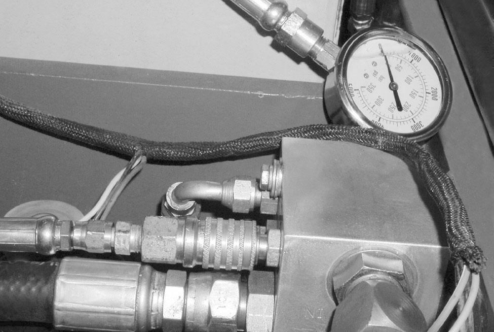
Loosen the lock nut (1) and turn the adjusting screw (2) counterclockwise to increase and clockwise to decrease the pressure.
NOTE: One turn of the adjusting screw (2) will change the pressure approximately 500 PSI (35 bar).
Hold the adjusting screw (2) from turning and tighten the lock nut (1). Repeat Steps 40 and 42 until the counterbalance release pressure is 1500 psi (103 bar).
If the adjusting screw does not change the pressure, repair or replace the load check valve cartridge.
Template Name: OML_2_col
Template Date: 1994_04_22
0-00000
844/642 Telehandler HYDRAULICS
Extension Cylinder Quick Test
STEP 44
Install a 5000 psi pressure gauge and hose on the port labeled “MP” of the flow divider.
NOTE: The hose must be long enough to observe the pressure gauge from inside the cab or standing clear of the forklift.
STEP 45
Start the engine and run at 1000 RPM. Retract the boom until the boom extension cylinder is at the end of its stroke and hold the joystick in the RETRACT position. The pressure gauge should read 3000 psi (207 bar).
If the pressure is more than 3000 psi (207 bar) proceed to the Main Control valve Pressure Relief Test and Adjustment section of this manual.
If the pressure is less than 3000 psi (207 bar), proceed to the next step.
If the pressure is 3000 psi (207 bar), but the extension cylinder is not working properly, check the boom or extension cylinder barrel for damage.
Step 46
Lower the boom until the lift cylinders are at the end of their stroke and hold the joystick in the BOOM LOWER position. The pressure gauge should read 3000 psi (207 bar).
If the pressure is less than 3000 psi (207 bar), proceed to the Main Control Valve Pressure Relief Test and Adjustment section of this manual before proceeding to the next step.

If the pressure is 3000 psi (207 bar), proceed to the next step.
Extension Cylinder Direct Test
STEP 47
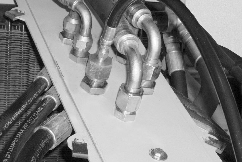
Shut off the engine. Remove the hose (1) from the retract bulkhead fitting (2). Install a 5000 psi pressure gauge and adaptor (3) on the bulkhead fitting (2) and plug the hose (1) end.
Template Name: OML_2_col