Template Name: OML_2_col Template Date: 1997_02_12
907871E
Alt= to hide template information Alt+ to display template information
844/642 Telehandler
ELECTRICAL
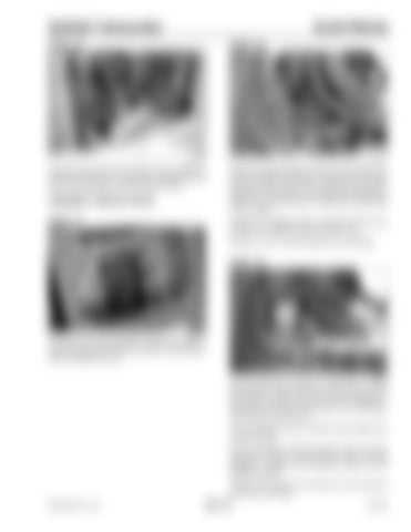
STEP 36
STEP 38
G0705102
G0705107
Connect the frame wire harness to the stabilizer cylinder solenoid wire connectors. Repeat Step 33 for the other stabilizer cylinder solenoid valve.
Disconnect the proximity switch from the frame wire harness. Install the positive (+) test lead in the brown wire recepticle of the wire harness plug and the negative (-) test probe in the black wire recepticle. With the key switch ON the multimeter should read 12 to 13 volts.
PROXIMITY SWITCH TESTS STEP 37
If there is no voltage repair or replace the brown wire between the stabilizer cylinder and the fuse. If there is 12 to 13 volts proceed to the next step.
STEP 39
G0705086
Check the park brake/stabilizer cylinder fuse (#2) (1) and test the power to the fuse (Step 4) and ignition relay (2) (Steps 5 and 6). G0705110
Set the multimeter to OHMs or CONTINUITY. Install the positive (+) test lead in the brown wire prong of the proximity switch connector and the negative (-) test lead in the black wire prong. The multimeter should read an open circuit. If the multimeter shows a closed circuit replace the proximity switch. If the multimeter shows an open circuit, but the stabilizer cylinder is restricting the frame leveling op eration , r eplace the solen oid valves on th e stabilizer cylinder. Connect the frame wire harness to the proximity switch wire connector. PRINTED IN U.S.A.
301-19
913250


