Template Name: OML_2_col Template Date: 1997_02_12
907871E
Alt= to hide template information Alt+ to display template information
844/642 Telehandler
ELECTRICAL
PARK BRAKE CIRCUIT TESTS
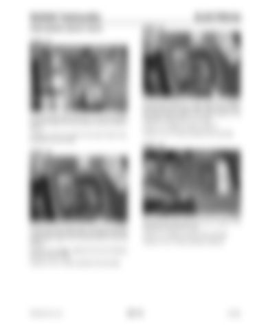
STEP 24
STEP 22
2
1
G0705100
G0705091
Check the park brake fuse (#2) (1) and test for power to the fuse (Step 4) and the ignition relay (2) (Steps 5 and 6). If there is 12 to 13 volts at the park brake fuse, proceed to the next step.
Connect the positive (+) test lead to the bottom terminal (#2) of the relay socket. With the key switch and par k brake switch in the ON p ositio n, th e multimeter should read 12 to 13 volts. If there is no voltage, proceed to Step 31. If there is 12 to 13 volts, proceed to the next step.
STEP 25 STEP 23
G0705085 G0705099
Remove the park brake relay. Connect the positive (+) test lead to the right side terminal (#4) of the park brake relay socket. Turn the key switch to the ON position.
Move the park brake switch to the OFF position. The multimeter should read 0 volts. If there is no voltage, proceed to the next step. If there is 12 to 13 volts, proceed to Step 28.
If there is no voltage, replace the red wire between the fuse and the relay. If there is 12 to 13 volts, proceed to the next step.
PRINTED IN U.S.A.
301-15
913250


