Template Name: OML_2_col Template Date: 1997_02_12
Rac 0-00000
Alt= to hide template information Alt+ to display template information
844/642 Telehandler
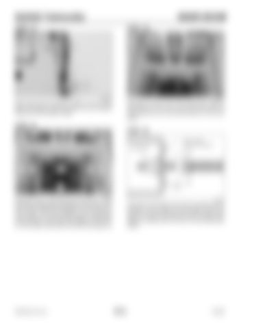
INNER BOOM
STEP 33
STEP 35
1
1
2 G0605090
G1640MP
Reconnect the two hydraulic hoses (1) to the tube lines connected to the tilt cylinder and the support block (2) on the auxiliary hoses.
Reinstall one of the nuts on the single chain clevis so that a bo ut 2-3 /4 in ch (7 0 mm) o f th e clevis is extending from the mounting bracket on the inner boom.
STEP 34
1
3
STEP 36
2
2
4
3
1
4 G1609MP
Reinstall the four side slide pads and shims (1) and the two top slide pads and shims (2) to the rear of the inner boom using the lockplates (3) and bolts (4). Use Loctite 271 (red) Thread Lock (or equivalent) on the threads of the bolts and tighten to 30 ft.-lbs. (41 Nm) torque. Bend each end of the lock plates up.
PRINTED IN U.S.A.
G1607MS
Pull back on the single chain clevis to position the nut between the two bars on the bracket. Check the amount of clevis extending from the bracket, then adjust to achieve the 2.75 inch (70 mm) dimension shown.
703-6
913250


