Template Name: OML_2_col Template Date: 1994_04_22
0-00000 Alt= to hide template information Alt+ to display template information
844/642 Telehandler
HYDRAULICS
STEP 41
STEP 43 If a new counterbalance valve was installed, repeat Steps 40 and 42 to set the load check valve release pressure. Remove the pressure gauge from the cylinder and install the supply hose on the cylinder port.
G0805029
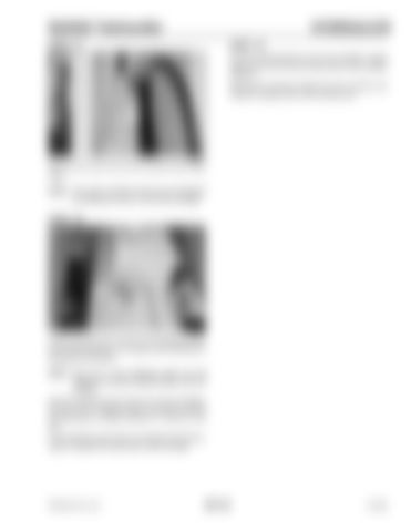
Remove the cover from the tilt cylinder load check valve. NOTE: The cover is friction fit and can be loosened by twisting the cover on the valve cartridge.
STEP 42
1
2 G0805030
Loosen the lock nut (1) and turn the adjusting screw (2) counterclockwise to increase and clockwise to decrease the pressure. NOTE: One turn of the adjusting screw (2) will change the pressure approximately 500 PSI (35 bar). Hold the adjusting screw (2) from turning and tighten the lock nut (1). Repeat Steps 40 and 42 until the counterbalance release pressure is 1500 psi (103 bar). If the adjusting screw does not change the pressure, repair or replace the load check valve cartridge.
PRINTED IN U.S.A.
601-23
913250


