Template Name: OML_2_col Template Date: 1994_04_22
0-00000 Alt= to hide template information Alt+ to display template information
844/642 Telehandler
HYDRAULICS
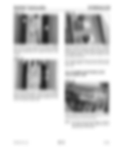
STEP 33
STEP 35 2
1
G0805024
G0505046
Shut off the engine. Remove the pressure gauge from the tilt up supply hose (1) and remove the cap from the cylinder por t (2). Install the hose on the cylinder.
Start the engine and run at 1000 RPM. Hold the joystick in the TILT DOWN position until the cylinder reaches the end of its stroke. Hold the joystick in the TILT DOWN position. The pressure gauge should read 3000 psi (207 bar).
STEP 34 If the pressure gauge reads less than 3000 psi (207 bar), repeat Steps 31, 32 and 33 for the tilt down relief valve.
TILT CYLINDER COUNTERBALANCE VALVE QUICK TEST
1 2 3
STEP 36
G0805026
Remove the supply hose (1) from the rod (tilt down) port (2) of the tilt cylinder. Cap the cylinder port and install a 5000 psi (345 bar) pressure gauge and hose (3) on the cylinder supply hose.
G0805005
Install a 5000 psi (345 bar) pressure gauge and hose on the MP test port of the flow divider. NOTE: The hose must be long enough to observe the pressure gauge from inside the cab or standing clear of the forklift.
PRINTED IN U.S.A.
601-21
913250


