Lubrication Systems A.
DESCRIPTION
Lubricating pump is a four lobe internal gear pump. The pump is driven by a gear on the camshaft. The pump has a build-in relief valve to limit maximum pressure. B.
OIL PUMP
1.
REMOVAL
a)
Remove the oil pan drain plug and drain the oil while the engine is warm.
b)
Install the drain plug then remove the bolts securing the oil pan to the crankcase and, remove the oil pan and adapter plate.
c)
Remove the bolt (1-1) securing the oil pump (2-1) to the crankcase and withdraw the oil pump.
2.
LOBE TYPE
a)
Remove the two bolts (2-3) which secure the oil pump screen (1-3) to the pump body cover (3-3) and remove the screen.
b)
Drive out roll pin (3-4) then remove the coupling (2-4) and pinion (4-4) from the shaft.
c)
Remove bolts (4-3) which secure the cover to the body.
d)
Remove cover (12-4).
(e)
Remove the shaft assy. (7-4) from the pump body (5-4).
(f)
Remove Retainer plug (19-4) then lift out regulating spring (17-4) and relief valve (16-4) and gasket (18-4).
3.
INSPECTION & REPAIR
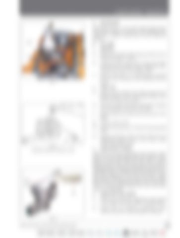
Fig. 1
Fig. 2 Checking clearance between rotors
Check the oil pressure regulating valve spring. Check the oil pressure regulating valve and seat for wear, pitting, or corrosion. Check the drive shaft to pump body clearance. Check the drive spin-on for wear or damage. Check the clearance between the lobes of the rotor (Refer Fig.2). It should not be more than 0.25 mm. Check the clearance on the end of the rotors. Check the clearance between outer rotor and rotor pocket (Refer Fig.2). The clearance should not be more than 0.3 mm. Always service/replace the inner and outer rotors as an assembly. 4.
INSPECTION AND REPAIR
a)
Check the oil pressure regulating valve spring (17-4) against the loads given in specifications.
b)
Check the oil pressure regulating valve (16-4) and seat for wear pitting or corrosion.
Fig. 3 35 Series 4WD, Model - 3535, 4035, 4535 and 5035 SM June’08
C-43


