
3 minute read
4. FUNCTIONING OF FLOW CONTROL VALVE


The Control Valve has three distinct functioning phases:
A)NEUTRAL PHASE
B)DELIVERY PHASE
C)DISCHARGE PHASE
A.NEUTRAL PHASE
In this phase the control valve keeps under pressure the oil in the cylinder bearing the load while the oil coming from the pump flows freely into the tank.
The control spool (1) is in the position to connect chamber (26) of the pilot valve (27) directly to the discharge through hole (16). Thus allowing the same valve to open hole (28) which discharges chamber (15) by means of the duct (29) of the regulator piston (2). Thus the oil coming from the pump feeds chamber (22) and allows the regulator piston (2) to open the holes (17) and the oil flows to the tank.
The oil contained in the cylinder (23) remains under pressure by means of the check valve (3), by the discharge valve (4) and by the safety valve (5) which are connected to the cylinder by the annular duct (18) and thus sustains the load applied to the lifting arms.
The safety valve (5) protects the cylinder from the possibility of eventual over-pressure due to the oscillation of the load during road transport.
B.DELIVERY PHASE
During this phase the Control Valve supplies oil under pressure to the cylinder (23) and this consequently lifts the arms.
The control spool (1) is in the position to connect chamber (26) of the pilot valve (27) with the oil coming from the pump through the annular duct (19) and the holes (20), (21) and (30) thus allowing the pilot valve to close itself. The oil coming from the pump feeds at the same pressure chamber (22) and chamber (15) (through duct - 29) of the regulator piston (2) that closes the discharge holes (17) due to the upward push of the return spring.
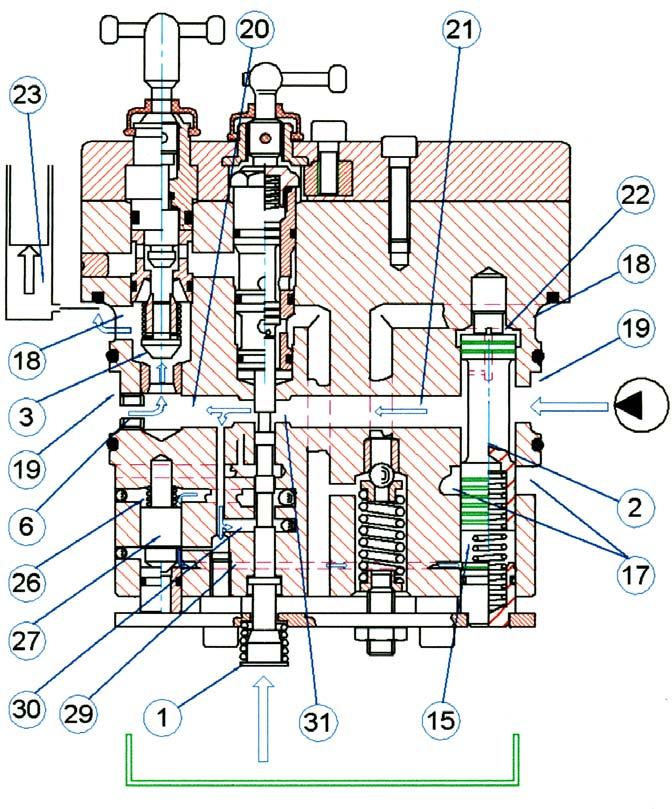
The oil under pressure flows to the cylinder through the annular duct (19, enters in hole (20) through the fixed throat (6) and the variable throat made by the control spool (1) with the hole (21), opens the check valve (3), enters in the annular duct (18) and feeds chamber (23) of the cylinder.
The regulator piston (2) regulates the oil flow of the cylinder because chambers (15) and (22) are subject to the difference in pressure created by the oil in the passage through the variable throat (31) which is opened or closed by the control spool (1).
The excessive flow Is deviated on the rising pressure from holes (17), thus regulating the maximum lifting speed and allowing a slow and smooth starting and arrival of the lifting arms.
The maximum lifting pressure is controlled by a relief valve placed on the body of rock shaft connected to the inlet port of oil coming from the pump.
C. DISCHARGE PHASE
During this phase the Control Valve supplies to the discharge both the oil coming from the pump as well as the oil coming from chamber (23) of the cylinder, with the consequential lowering of the lifting arms.
The control spool (1) is in the position to connect chamber (26) of the pilot valve (27) directly to the discharge through hole (16), thus allowing the same valve to open hole (28) that flows to the discharge through duct (29) chamber (15) of the regulator piston (2). The oil coming from the pump, as in the neutral phase, is able to move the regulator piston towards chamber (15) that opens the discharge holes (17) causing oil to flow to the tank.

At the same time the oil from the cylinder under pressure (chamber - 23) enters in the annular duct (18) passes through the holes (32), the valve (8) and hole (24) enters in the discharge valve (4) flowing to the tank from hole (25), causing the lowering of the arms.
In this phase the lowering speed of the arms can be regulated by the manual lever "RD" (by screwing the lever clockwise the lowering speed decreases).
For road transport, in order to avoid the accidental lowering of the rockshaft arms due to the movement of the levers, screw shut the lever "RD", this completely closes the valve (8) in its seat in order to close the passage between the chamber (23) of the cylinder and the discharge valve (4).
The cylinder is always protected by accidental over-pressure by the safety valve (5).


