1 minute read
Hydraulics


7.Remove cam (J) and allen set screws (k).
8.Loosen the allen set screw (L) of crank (M) and remove control lever support assembly by loosening bolts (N) and take out control lever support assembly.
9.Remove roll pin (O) of cam (P) and snap ring.
10.Remove capscrew (Q) of tie rod (R) and pin assembly (S).
NOTE:Ins pect bushings for wear or damage. Replace as necessary.
11.Reverse the dismantling procedure for assembly and installation.
NOTE:Apply thread sealant to allen set screws during assembly.
12.Adjust hydraulic lift unit position and draft sensing feedback linkages.
Hydraulics
14.REMOVE, INSPECT AND INSTALL HYDRAULIC RATE-OF-DROP VALVE
1.Open rate-of-drop valve and lower lift arms completely.
2.Remove seat.
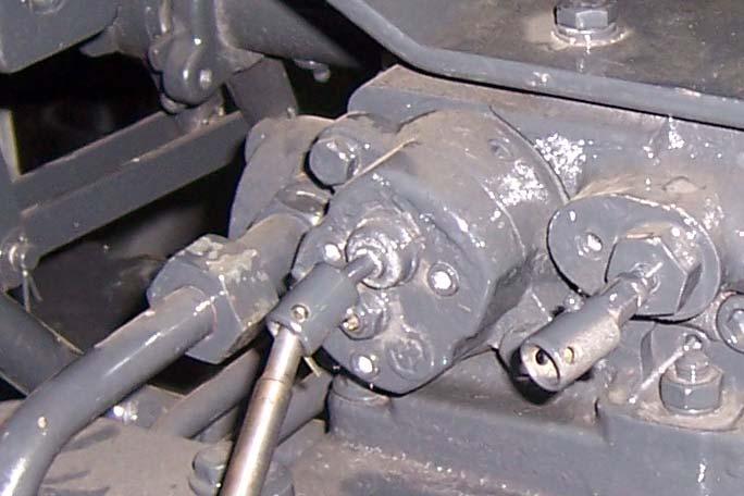
3.Remove cap screws (C) and remove rockshaft control valve (A).
4.Remove three socket head screws (B). Firmly grab tee handle and pull straight out, removing rate-of-drop valve assembly from rockshaft control valve.
5.Install new rate of drop valve and tighten bolts to specified torque 19-29 Nm (14-21 Lb-ft.).
6.Install seat.
7.Operate hydraulic.
8.Fill transmission / hydraulic oil as per the recommended grade and quantity.
9.Adjust hydraulic control valve.
Service Recommendation:
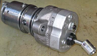
It is not recommended to repair Flow Control Valve. Flow Control Valve should be completely replaced, if internal problem suspected.
NOTE:Use O’Ring set (Seal kit - contains outer O’Rings of flow control valve) of flow control valve for replacement. Use protective sleeve to install O’Rings on flow control valve.


