13 minute read
Electrical System


7.TROUBLE SHOOTING FLOW CHART FOR ALTERNATORS
SERVICE RECOMMENDATIONS :
Before dismantling Alternator from engine, make sure that Alternator is faulty. Below flow chart will help on diagnosing the fault. It is recommended to replace complete Alternator for any internal failure of Alternator. Not to disassemble the Alternator for repairing inside components.
SWITCH ON THE IGNITION
DOES WARNING LAMP GLOW?
YES
RAISE THE ENGINE SPEED TO 1000 RPM (APPROX)
CHECK WARNING LAMP FOR ANY DEFECT. CHECK “WL” TERMINAL IN ALTERNATOR FOR PROPER CONNECTION.
DOES WARNING LAMP GO OFF?
CONNECT DC AMMETER IN SERIES WITH ALTERNATOR & BATTERY POSITIVE TERMINAL. ENSURE THAT THE AMMETER READING FALLS BETWEEN 7 TO 10 AMPS. IN CASE THE BATTERY IS FULLY CHARGED THE AMMETER INDICATION MAY VARY. ALSO CONNECT THE VOLTMETER ACROSS THE ALTERNATOR MAIN TERMINALS. CHECK THE VOLTMETER READING.
DOES THE VOLTMETER READ BETWEEN 14.2 TO 15.0 VOLTS?
YES NO
CHECK THE BELT TENSION. IF FOUND SLACK ADJUST THE BELT DEFLECTION TO BE 10-15MM WHEN PRESSED MIDWAY AT THE LONGEST POINT BETWEEN PULLEYS (REFER FIGURE BELOW) AND CHECK FOR CHARGING. IF THE UNIT IS STILL NOT CHARGING REMOVE THE ALTERNATOR AND CHECK.
REMOVE THE ALTERNATOR AND CHECK REGULATOR
SWITCH “ON” THE HEAD LAMP PARKING LAMP, TAIL LAMP AND OTHER ELECTRICAL LOADS EXCEPT HEATER.
IS RATED CURRENT OUTPUT
YES NO
REACHED WITHOUT VOLTAGE DROPPING BELOW 13.5 VOLTS ?
REMOVE THE ALTERNATOR AND CHECK YES
ALTERNATOR FOUND ACCEPTABLE
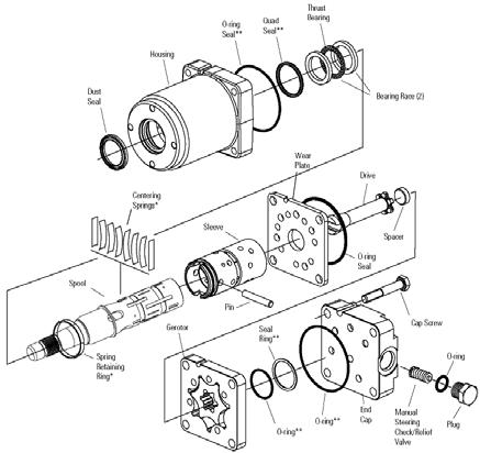
8.EXPLODED VIEW - ALTERNATOR
1.SPECIFICATION
a)Steering Control Unit
1.Make---------------------------------------------------------- EATON
2.Type----------------------------------------------------------- Open center non load reaction
3.Displacement ----------------------------------------------- 6.10 inch 3 / rev (100 cc/rev)
4.Relief valve setting --------------------------------------- 100 Bar
5.Rated flow-------------------------------------------------- 19 lpm b)Pump
1.Make---------------------------------------------------------- EATON
2.Type----------------------------------------------------------- Gear
3.Displacement ----------------------------------------------- 8 cc / rev c)Cylinder
1.Type----------------------------------------------------------- Double acting balanced d)Filteration --------------------------------------------------------- Strainer 100 mesh and suction line filter 10 micron common with hitch circuit e)Maximum Operating Temperature------------------------ 90 o C
2.Bore ----------------------------------------------------------- ø 63 mm (2.48 in.)
3.Rod------------------------------------------------------------ ø 38 mm (1.50 in.)
4.Stroke --------------------------------------------------------- 220 mm (8.66 in.)
3.REMOVAL & REFITMENT OF HSU UNIT
A.Removal a)Hose pipe of L & R ports. b)Hose from Hydraulic pump to HSU. c)Hose from HSU to PTO solenoid valve.
1.Remove the battery cables. Remove the Battery by removing the two stay bolts and the battery holding plate. Take away the Battery.
NOTE: Always disconnect the negative terminal first.
2.Disconnect the following hydraulic oil connections & Plug the pipes to prevent oil spillage.
3.First remove the steering wheel cap and steering wheel nut. Remove the steering wheel by loosening nut and use steering wheel puller to remove the steering wheel.
4.Dismantle the steering column cover, Disconnect the wiring harness to PTO engaging switch.
5.Dismantle the scuttle cover.
6.Remove linkages of hand accelerator and forward/reverse.
7.Loosen bolts of HSU Bracket.
8.Loosen hose connector of HSU to separate HSU.
In case any internal leakages observed, remove HSU unit to replace O'Rings (seal kit) as follows:
Hydraulics Steering Unit Removal (Ref Fig.)
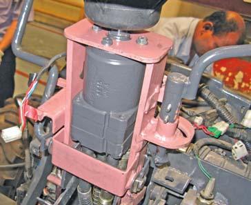
1.Loosen the cap screws of unit.
2.Gently take out the end cap.
3.Check the O’Rings for wear or damage.
4.Install the new O’Rings (seal kit) and fit the adaptor and tighten as per the specified torque of 25 Nm / 18 lb.ft.
5.Refit the removal parts of unit in reverse sequence of removal.
B.Refitment
1.Assemble HSU unit
2.Fit the HSU hose pipe, connections and bracketaries.
3.Connect the linkages of hand accelerator and forward/reverse.
4.Assemble scuttle cover.
5.Fit the steering wheel and cap.
Recommended Practices for Handling and Storage of Hydraulic Components
The life of every hydraulic system is directly related to system cleanliness. Typically, the cleaner a system is, the longer it will last. Particle or chemical contamination, therefore, is the enemy of any hydraulic system and extra effort should be taken to avoid contamination whenever and wherever possible. The following is a list of good practices to reduce or eliminate potential contamination while storing, handling, assembling and using hydraulic system components.
Ports & Fittings
•Port plugs should remain in components and hoses until ready to use.
•Use care in removing port plugs so that plastic does not shear off in threads.
•Use caution to ensure excess paint near the port face does not chip off or fall into the unit.
•The area around the port face is a sealing surface and should be protected from dents or contamination.
•Fittings being screwed into the port should be kept clean and lubricated.
Assembly & Storage
•Hose and tube assemblies should be flushed and capped until used.
• Never use shop air to blow out a tube, hose or reservoir as the air supply may not be “clean” air.
•Filler caps should be kept clean.
•Hydraulic assembly areas should be free of airborne contaminants.
•If components are stored in a cold environment, be sure to remove any condensation that may occur as the components warm up.
•If storage is prolonged, components may need to be rust proofed.
Fluids
•Hydraulic fluid should be filtered to ISO 18/13 or better for initial fill.
•Water and hydraulic fluid do not mix; water is considered a foreign chemical contaminant.
•Any surface in contact with hydraulic fluid must be clean and dry.
•Random sampling should be taken from hydraulic systems on vehicles ready to ship to ensure cleanliness level meets ISO 18/13 or better.
Exposed Surfaces
•Exposed cylinder rods should be handled with care to avoid scratches and dents.
•Motor and pump shafts should be kept clean and free of physical damage. Splines should be coated with anti-seize compound or grease before assembly.
Tapered shafts should also be protected from physical damage to the shaft and coupling ID.
Returns
If there is a suspected problem with a new startup component, remove the component and protect it for later analysis. In the event a component must be returned to Eaton or Mahindra dealer do NOT disassemble the unit and use only lint-free rags to wipe components.
NOTE: Units returned to Eaton require a returned goods authorization assigned BEFORE shipping.
SINCE SOLVENTS ARE FLAMMABLE BE EXTREMELY CAREFUL WHEN USING THEM EVEN A SMALL EXPLOSION OR FIRE COULD CAUSE OR INJURY.
Eye protection should be worn.
ADDITIONAL NOTES :
1)Fluid too thick to flow in cold weather startup will cause pump cavitation and possible damage motor cavitation is not a problem during cold start-ups. Thick oil can cause high case pressure which in turn can blow pump shaft seals.
2)If the natural colour of the fluid has become black it is possible that an overheating problem exists.
3)If the fluid become milky, water contamination may be a problem.
4)Take fluid level reading when system is cold.
5)Contact your dealer-representative if you have specific questions.
Steering System Circuit
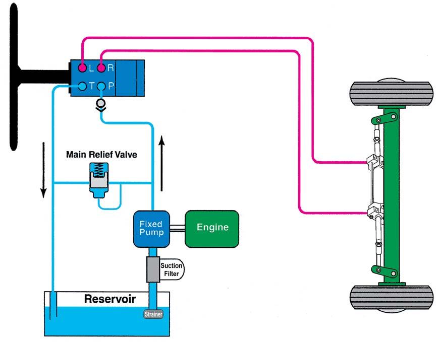
4.DESCRIPTION
The power steering is of the hydrostatic type, linked by fluid, there being no mechanical connection between the steering wheel and front axle. The system consist of an engine driven pump, control valve, a hydraulic cylinder and suction line filter. Manual pump and control valve are integrated to form a compact steering unit. Figure show a schematic drawing of the system. This is open centre, non load reaction type system. Turning the steering wheel delivers fluid to move the spool valve against its centering spring. This then directs the delivery of fluid to the inlet side of the manual pump, passing through the pump and the control valve to the steering cylinder. This in turn supplies the required steering effort according to the rate of steering wheel turn. The only manual effort required is that necessary to over come the control valve centering spring. The stiffness of the spring has been selected to give the desired feel and self-straightening effect.
Manual steering is accomplished in the same manner when the engine is running, except that there is no power assistance. By rotating the steering wheel, the manual pump delivers fluid through the control valve to the steering cylinder. A check valve in the control valve provides for the return of fluid from the cylinder to the manual pump instead of to the reservoir, to complete the circuit.
a.Manual Steering Effort
This circuit consists of the manual pump, control valve and steering cylinder. Hydraulic fluid circulates in the closed circuit from manual pump, through the control valve to the steering cylinder, and returns from the steering cylinder through the control valve back to the manual pump.
Initial movement of the steering wheel in either direction develops pressure (15 to 20 lb/in2) which actuates the control valve spool. The movement of the control valve spool opens the ports from the manual pump to the steering cylinder and return ports from the steering cylinder to the manual pump.
The resistance of the wheels determines the steering effort required by the operator to develop the necessary hydraulic pressure at the steering cylinder piston to turn the wheels. The manual pump attached to and driven by the steering wheel develops the necessary pressure.
The initial effort to turn the steering wheel in either direction instantly increases hydraulic pressure in the manual pressure line, while the pressure in the suction line remains static or in lowered. Since the manual pump and the control valve are part of the closed hydraulic circuit, this same difference in pressure exists between the ends of the control valve spool. Were it not for the centering spring, the spool would instantly move toward the lower pressure end. Very little force is required at the steering wheel rim to create a pressure difference of 15 to 20 lb/in2, the pressure necessary to over come spring resistance. The spool then moves, diverting fluid to the steering cylinder.
Continued turning of the steering wheel moves the fluid to and through the control valve to the steering cylinder and against the cylinder piston.
Therefore, as pressure against the cylinder causes it to move. Turning the wheels an equal amount of displaced fluid moves, under pressure from steering cylinder to the control valve, it unseats a re-circulating check ball connecting the engine driven pump pressure inlet chamber and the cylinder return chamber. This allows the fluid to move through the passage in control valve spool and back to the manual pump to complete the cycle.
The displaced fluid does not return to the reservoir even though the reservoir return line is open because of the suction created in the manual pump.
The engine driven pump being stopped, the fluid in the power circuit and the reservoir is under no pressure and is therefore static.
The re-circulating check ball is seated under pressure when engine driven pump is operating.
b.Power Steering
This circuit consists of reservoir, engine driven pump, control valve, manual pump and steering cylinder. The initial turn of the steering wheel develops the 15 to 20 lb/in 2 pressure differential in the manual pump lines at the control valve spool to direct the incoming high pressure fluid from the engine driven pump to the manual pump inlet.
A small amount of steering effort must always be supplied throughout a turn to add the extra 15 to 20 lb/in2 pressure to whatever the pump is supplied to the manual pump. This gives “steering feel” while providing sufficient force to over come the resistance of the control valve spool centering spring.
As soon as the manual steering effort ceases, the 15 to 20 lb/in 2 pressure differential in the manual pump to control valve spool centres and the fluid in steering circuit becomes static. The fluid moving from the engine drive pump into the centered control valve is directed back onto the reservoir.
Fluid from the engine driven pump is directed by control valve to manual pump inlet or returned to the reservoir when not needed. Fluid supplied by the engine driven pump never goes directly to the steering cylinder.
i.Turning :
The initial turn of the steering wheel driving the attached manual pump, moves the control valve spool and opens the port to the manual pump and the steering cylinder. The fluid from the engine driven pump enters the control valve and this fluid passes through the control valve spool passage into the manual pump. The fluid the passes through and out of the manual pump under high pressure to and through the control valve to the steering cylinder and against the cylinder piston. An equal amount of fluid displaced by the moving piston flows to the control valve under low pressure and return to the reservoir to supply the engine driven pump.
ii.Neutral
With no steering at the manual pump, the control valve spool is in the centered or neutral position. Fluid in the closed manual steering circuit is static. With the spool centered fluid flow from the engine driven pump is directed through the open control valve channels back to the reservoir. When the steering wheel is turned to move the valve spool off its centered position this fluid is instantly available.
Service Recommendation:
It is not recommended to repair pump. Pump should be completely replaced, if internal problem suspected.
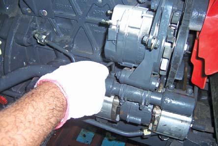
5.REMOVAL & REFITMENT OF STEERING PUMP
A.Dismantling the Steering Pump
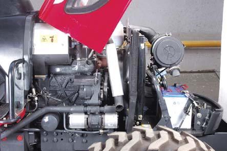
1.Unlock the Hood lock and lift the hood.
2.Remove RH side panel.
3.First remove the battery cable from its negative terminal. Then remove the same from its positive terminal.
4.Disconnect the Steering Pressure Line (B) of steering pump (A) by loosening the pipe nut.
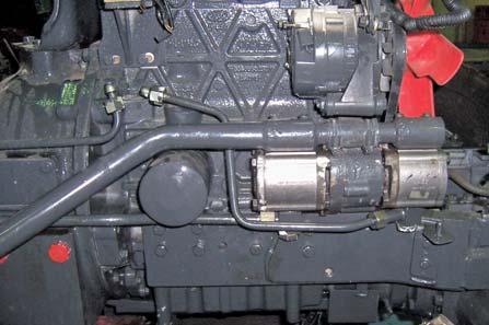
5.Disconnect the Suction Line (C) by loosening the cap screws (D).
NOTE: Close all openings with caps and plugs.
6.Remove both Pumps for further repairs or replacement.
B.ASSEMBLING THE STEERING PUMP
Always use new O’Rings. Damaged or used O’Rings will leak.
1.Place new O’Rings on pump flange. Install pump on engine.
2.Install cap screws for connecting the Hydraulic Suction Lines.
3.Connect the Steering Lines and Hydraulics Pressure lines.
NOTE: Hold adapters when tightening Hydraulics / Steering lines to eliminate overtightening of adapters on pump.
4.Connect the Battery connections.
5.Fit the RH side panel and close the hood.
6.Start engine and operate hydraulics. Check all connections for leaks.
7.Check oil level, add if necessary with the recommended grade of oil.
6.AIR BLEEDING THE SYSTEM
1.Maintain the oil level in transmission housing by means of dipstick. Be ready to add oil when the engine is started.
NOTE: This oil will be circulated only from the power pump to and through part of the HSU control valve and to the power steering pump. When more oil can be added and oil is clear proceed as follows:
3.Turn the steering wheel alternately left and right, approx. 10 times avoiding, however that wheel contact their front axle stops. Turn steering wheel twice to each side.
4.After venting it is recommended to jack up the front axle, especially if steering cylinder is removed.
Do not operate vehicle until air is bleed out.
5.Maintain recommended oil level in reservoir and assemble reservoir cap.
7.TIPS FOR MAINTAINING THE HYDROSTATIC STEERING SYSTEM
•Top up fluid level in reservoir (transmission housing) if necessary.
•Maintain correct inflation pressure in front tire.
•Always use a puller to remove the steering wheel. Do not use a hammer, torch, or crow bar.
•Investigate and correct immediately any play, raffle, shimmy, or other unusual occurrence in the steering system.
•Do not attempt to weld any broken steering component. Replace the component with original equipment only.
•Do not cold straighten, hot straighten, or bend any steering part.
•Prevent dirt or other foreign matter from entering the hydraulic system. Clean off around filler caps before checking oil level. Investigate and correct any external leak in the steering system, no matter how minor the leak.
•Clean or replace the filter as per the routine service schedule.
8.Removal of Steering Cylinder from Tractor a.Jack up the tractor. b.Open the hood. c.Disconnect both hoses from HSU to Steering cylinder. d.Plug both ends of the hoses to prevent entry of dust. e.Remove plastic ties binding the axle breather hose and push the hose below battery mounting plate towards the axle. f.Close the hood. g.Hold the front axle with ropes. h.Remove both front wheels. i.Remove front & rear propeller shaft guards. j.Remove propeller shaft sleeve at transmission case end. k.Disconnect Propeller shaft bearing from bearing bracket. l.Slide the propeller shaft towards axle first and then slide away from the axle. m.Remove mounting bolts holding axle to semichassis. n.Move the axle away from the tractor. o.Remove both connecting links connected to axle & steering cylinder. p.Remove Steering cylinder mounting bolts from axle. q.Move away the steering cylinder.
9.Inspection a)Thoroughly wash all components in clean solvent and blow dry with compressed air. b)Check the cylinder bore for scratches or grooves. c)Inspect the cylinder bore that is out of round must be replaced. d)Inspect the piston and piston rod for scratches and wear, then check the piston rod or straightness. e)Inspect the piston rod bearing for excessive wear or damage.
Visually inspect all parts and replace those parts which are not in good condition. Inspect cylinder bore finished surface and piston surface. Piston rod surface. Inspect for abnormal wear scoring or damage.
10.Assembly a)Coat all internal parts with clean hydraulic fluid. b)Renew the O’rings and wiper seal then assemble in the reverse order to dismantling. NOTE:Discard and replace all seals, gaskets, O’rings etc. Whenever a unit was taken down for repair.
Do not attempt to lap or rework mated parts with a high precision fit as this will cause internal leakage.
11.Adjustment
On these tractors full piston stroke of the steering cylinder is not utilized, but front wheels are stopped by regular steering knuckle stopper. Stoppers are factory adjusted and welded to give a definite front wheel angle in lock position.
1.Place front wheel in central position and check toe-in if necessary. Adjust tie rod length to obtain a toe-in of 0.07” to 0.23”.
2.Mount steering cylinder pre-assembled to specified length, to axle and steering lever.
3.Jackup tractor front axle. Turn wheels to both directions, full lock, and make sure inside wheels are stopped by lock stopper and not by the end of piston stroke.
4.With inside wheels in full lock position. Make sure there is a clearance of 0.004” between front stopper of the outer wheels and front axle stop.
5.Connect up pressure lines to their correct cylinder port.
6.Tighten lock nuts of ball joints.
12.Testing
a.Unit may be tested after installation on the machine.
b.Remove the air as per procedure given in point no.6.
c.With the tractor standing on dry concrete and the engine running at govern speed, operate the steering for approximately five minutes.
d.With the engine stopped it should be possible to rotate the steering from straight ahead to full lock in approximately six seconds.
e.With the engine running at rated speed and tractor standing on dry concrete, input torque should not exceed 3.8 Nm.
f.Stop the engine, and using the special spanner and a spring balance in the hole further from the end check input torque does not exceed 11.4 Nm Response must be insantaneous.
Check the both directions.
g.With the engine running at maximum rev/min. and steering wheel turned appropriate lock the pressure of 100 Bar must be recorded on a gauge fitted to one of the cylinder hose.
h.With the engine running at rated speed hydraulic oil temperature at 55 0 C ± 5 0 C. Turn the wheels to the extreme left and right lock and with a torque of 11.3 Nm.at steering shaft, check steering slippage does not exceed 3 rev/min.
NOTE:If no suitable torque wrench is available, the above slippage test can be made with a spring scale. A pull of approx. 8.8 lbs. at the steering wheel rim equals the necessary test torque 6 lbs/ft.
i.Testing the power steering internal leakage before and after repair.
a)Fill the cylinder with hydraulic fluid (testing oil) b)Connect a nozzle test pump to the inlet port of the filled cylinder side. c)Apply test pressure to determine leak oil volume. See “Specifications”.
NOTE:A sm all amount of external leakage (an oil moistered piston rod) is acceptable.
13.Trouble Shooting General
When steering problems are encountered, the following points should be checked first before proceeding with fault spotting.
•Oil level in reservoir.
•Suction pipe and return oil filter condition.
•External oil leakage.


